Fuel cell system

A fuel cell system and fuel cell technology, applied in fuel cells, power system fuel cells, batteries, etc., can solve problems such as battery degradation

Pending Publication Date: 2021-12-03
TOYOTA JIDOSHA KK
View PDF1 Cites 0 Cited by
  • Summary
  • Abstract
  • Description
  • Claims
  • Application Information

AI Technical Summary

Problems solved by technology

Therefore, if the actual generated power deviates greatly from the target generated power, the storage battery may become overcharged or overdischarged, resulting in deterioration of the storage battery.
[0007] In this way, when low-efficiency power is generated, the actual generated power tends to deviate greatly from the target generated power during the transition, so there is a possibility that the battery will be in an overcharged or overdischarged state, resulting in deterioration of the battery.

Method used


Image

  • Fuel cell system
  • Fuel cell system
  • Fuel cell system

Examples


Embodiment Construction

[0024] Hereinafter, embodiments of the present invention will be described in detail with reference to the drawings. In addition, in the following description, the same reference number is attached|subjected to the same component.

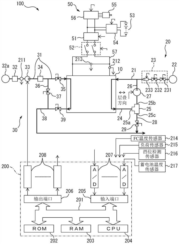
[0025] figure 1 It is a schematic configuration diagram of a fuel cell system 100 according to an embodiment of the present invention mounted on a vehicle.

[0026] The fuel cell system 100 includes: a fuel cell stack 10; a hydrogen supply device 20 for supplying hydrogen as an anode gas (fuel gas) to the fuel cell stack 10; and an air supply device 30 for supplying hydrogen as a cathode gas to the fuel cell stack 10. air (oxidant gas); an electrical load section 50 electrically connected to output terminals of the fuel cell stack 10 ; and an electronic control unit 200 for collectively controlling various control components of the fuel cell system 100 .

[0027] The fuel cell stack 10 is a member in which a plurality of fuel cell cells (hereinaf...


PUM


Abstract

The invention relates to a fuel cell system which suppresses deterioration of a storage battery in rapid warm-up operation. A control device (200) is provided with: a supply flow rate control unit for controlling the supply flow rate of the oxidant gas supplied to the fuel cell (10); and a power generation implementation unit that implements low-efficiency power generation with greater power generation loss than normal power generation. In the implementation of low-efficiency power generation, when the state of a mounting body on which a fuel cell system (100) is mounted is a first mode, a supply flow rate control unit controls the supply flow rate of an oxidant gas such that the amount of heat generated by a fuel cell (10) accompanying power generation loss becomes a first amount of heat. The supply flow rate control unit controls the supply flow rate of the oxidant gas such that the heat generation amount becomes a second heat generation amount that is smaller than the first heat generation amount when the state of the mounting body is a second mode in which the power generated by the fuel cell (10) varies more easily than in the first mode.

Description

technical field [0001] The present invention relates to fuel cell systems. Background technique [0002] Patent Document 1 discloses, as a conventional fuel cell system, a fuel cell system in which the self-heating value of the fuel cell is increased by performing low-efficiency power generation in which power generation loss is larger than normal power generation. Rapid warm-up operation for rapid warm-up of the fuel cell. [0003] Patent Document 1: Japanese Unexamined Patent Publication No. 2008-269813 [0004] During low-efficiency power generation, since the concentration overvoltage is increased to increase the power generation loss, the flow rate of the oxidant gas supplied to the fuel cell is smaller than that during normal power generation if the generated power is the same. That is, the target value of the air stoichiometric ratio (the ratio of the supply flow rate of the actually supplied oxidant gas to the supply flow rate of the oxidant gas minimally required ...

Claims


Application Information

Patent Timeline
Patent Type & Authority Applications(China)
IPC IPC(8): H01M8/04746H01M8/04223B60L50/70
CPCH01M8/04753H01M8/04268B60L50/70H01M2250/20H01M2220/20H01M8/04992H01M8/0494H01M8/04619B60L50/75B60L58/12B60L58/40B60L58/30Y02E60/10Y02E60/50Y02T10/70Y02T10/7072Y02T90/12Y02T90/40H01M8/04225B60L53/54H01M8/04626H01M8/04947
Inventor 难波良一松尾润一常川洋之
Owner TOYOTA JIDOSHA KK
Why Eureka
Try Eureka