
Eureka
For R&D, Eureka makes reading and utilizing patents & technical documents easy.
Eureka AIR
Designed for self-driven R&D workflows. Generate viable solutions, solve complex R&D challenges, empower your innovation with AI.

Eureka Materials
Designed for material experts only. Revolutionize your material R&D, from search, analyze, to developing new materials.

TechResearch
Generate reliable direction feasibility study reports for your R&D in just a few steps.

TechSeek
Discover and master advanced knowledge NOW. Basics, ideas, possibilities, all at once.

TechMind
As an expert in R&D Theories, TechMind can generates customized viable solutions instantly.

TechRisk
Analyze your overall solution with one click, know your potential R&D risks in advance.

TechMonitor
Get weekly tech updates, stay abreast of the latest tech innovations and key insights.
Sliding component
A technology of sliding parts and parts, applied in the direction of engine components, sliding contact bearings, bearing components, etc., can solve problems such as inability to exert stable sealing performance
- Summary
- Abstract
- Description
- Claims
- Application Information
AI Technical Summary
Problems solved by technology
Method used
Image

Examples
Embodiment 1
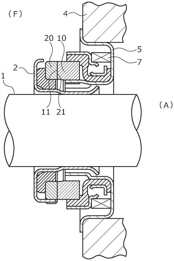
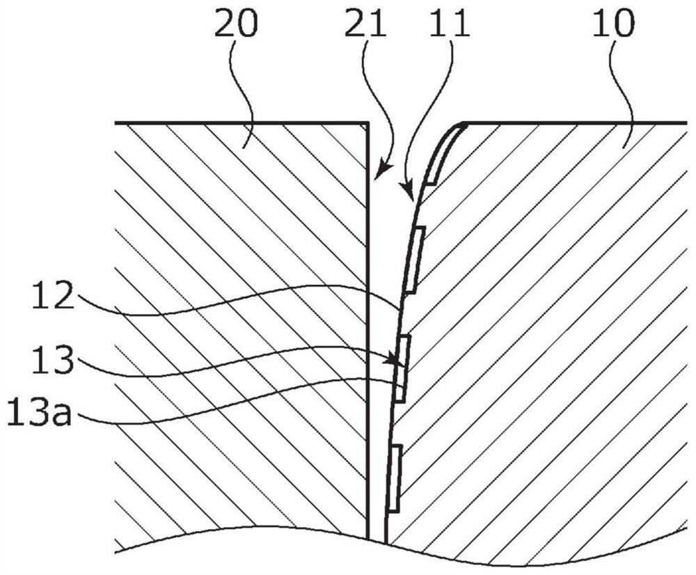
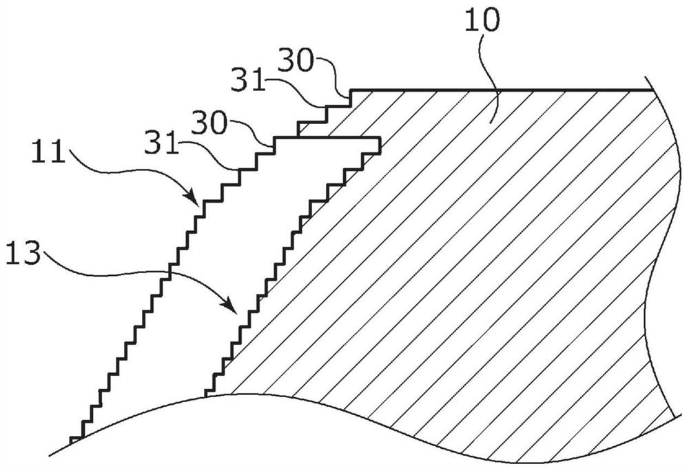
[0034] For the sliding parts involved in embodiment 1, refer to Figure 1 to Figure 6 , for illustration. In addition, in this embodiment, an example in which the sliding member is a mechanical seal will be described. In addition, the inside diameter side of the sliding member constituting the mechanical seal is the leakage side and the atmospheric side (low pressure side) of the gas side, and the outside diameter side is the sealed liquid side (high pressure side).
[0035] Such as figure 1 The shown mechanical seal for general industrial machinery is a built-in type, and seals the sealed liquid F that is intended to leak from the outer diameter side toward the inner diameter side of the sliding surface, and is mainly composed of a rotating seal ring 20 and a stationary seal ring 10, The rotary seal ring 20 is a ring as an annular sliding member, and is provided on the rotating shaft 1 in a state capable of rotating together with the rotating shaft 1 via the sleeve 2, and ...
Embodiment 2
[0061] Next, for the sliding member related to the second embodiment, refer to Figure 7 to explain. In addition, descriptions of configurations that overlap with those of the above-mentioned embodiments are omitted.
[0062] Such as Figure 7 As shown in (a), the facing surface 51 of the rotary seal ring 50 is formed in a convex curved shape in the facing direction, forming a curved surface. The opposing surface 41 of the stationary seal ring 40 is formed on a plane perpendicular to the axial direction. Thus, if Figure 7 As shown in (b), in the case where the rotary seal ring 50 is deformed when the rotating shaft 1 rotates, the facing surface 51 as its curved shape is inclined relative to the facing surface 41 of the stationary seal ring 40 as a plane. The region X3 centered on the closest portion P3 approaches, and a part of the facing surface 51 approaches in parallel with the facing surface 41 , thereby ensuring an effective facing region in the radial direction.
PUM
 Abstract
Description
Claims
Application Information
 - R&D Engineer
- R&D Manager
- IP Professional
- Industry Leading Data Capabilities
- Powerful AI technology
- Patent DNA Extraction
Browse by: Latest US Patents, China's latest patents, Technical Efficacy Thesaurus, Application Domain, Technology Topic, Popular Technical Reports.
© 2024 PatSnap. All rights reserved.Legal|Privacy policy|Modern Slavery Act Transparency Statement|Sitemap|About US| Contact US: help@patsnap.com