Dust removal equipment for textile processing

A kind of dust removal equipment and textile dust technology, applied in the field of textile processing, can solve the problems of affecting the quality of textile fabrics, single dust removal method, incomplete dust removal, etc., achieve stable dust removal effect, good dust removal effect, and avoid clogging

Inactive Publication Date: 2021-12-07
SSUZHOU KELANBO TEXTILE TECH CO LTD
View PDF5 Cites 0 Cited by
  • Summary
  • Abstract
  • Description
  • Claims
  • Application Information

AI Technical Summary

Problems solved by technology

However, the existing dust removal equipment for textile processing has a single dust removal method, and the dust removal is not thorough, and textile dust is likely to remain, which affects the quality of textile fabrics

Method used


Image

  • Dust removal equipment for textile processing
  • Dust removal equipment for textile processing
  • Dust removal equipment for textile processing

Examples


Embodiment 1

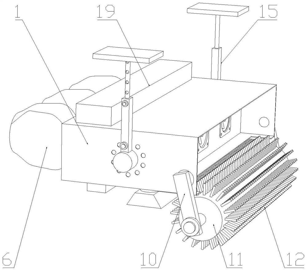
[0032] Such as Figure 1-5 As shown, a kind of dust removal equipment for textile processing proposed by the present invention includes a dust removal box 1, a mounting frame 2, a dust suction fan one 3, a filter plate 4, a dust suction fan two 5, a dust collection bag 6, a dust suction pipe 7, Dust collecting cover 8, dust removal assembly and controller; the dust inlet end opening of dust removal box 1; installation frame 2 and filter plate 4 are arranged in the inside of dust removal box 1 successively along the dust removal direction, and its internal space is divided into dust removal chamber 33 and The filter chamber 34; the installation frame 2 is provided with two groups; the dust suction fan one 3 is arranged on the dust inlet end in the dust removal box 1 through the installation frame 2; the dust suction fan two 5 is arranged on the dust outlet end of the dust removal box 1 of the filter plate 4 Above; the dust collection bag 6 is connected to the dust outlet end of...

Embodiment 2

[0035] Such as Figure 6 As shown, on the basis of the above-mentioned embodiments, the upper end of the dust removal box 1 in the present embodiment is provided with a cleaning assembly; On the upper end of the dust removal box 1; multiple groups of nozzles 20 are arranged, and the multiple groups of nozzles 20 are respectively located on both sides of the filter plate 4, and are all communicated with the liquid storage tank 19, and the nozzles 20 at the dust inlet end of the filter plate 4 spray liquid toward the filter plate 4. The spraying direction of the nozzle 20 located at the dust outlet end of the filter plate 4 is towards the liquid collection channel 21 downward; the bottom of the dust removal box 1 is provided with a liquid collection channel 21; the liquid collection bucket 22 corresponds to the position of the liquid collection channel 21 and is set The bottom of the dust removal box 1; the filter screen 23 is arranged in the liquid collecting bucket 22. The cl...

Embodiment 3

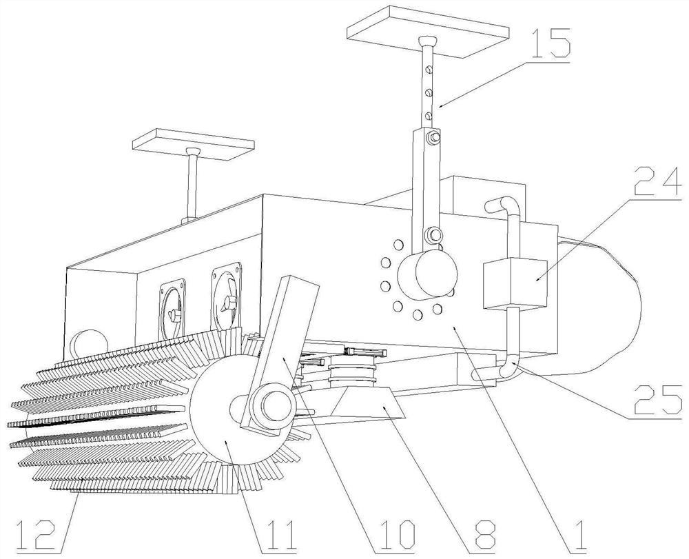
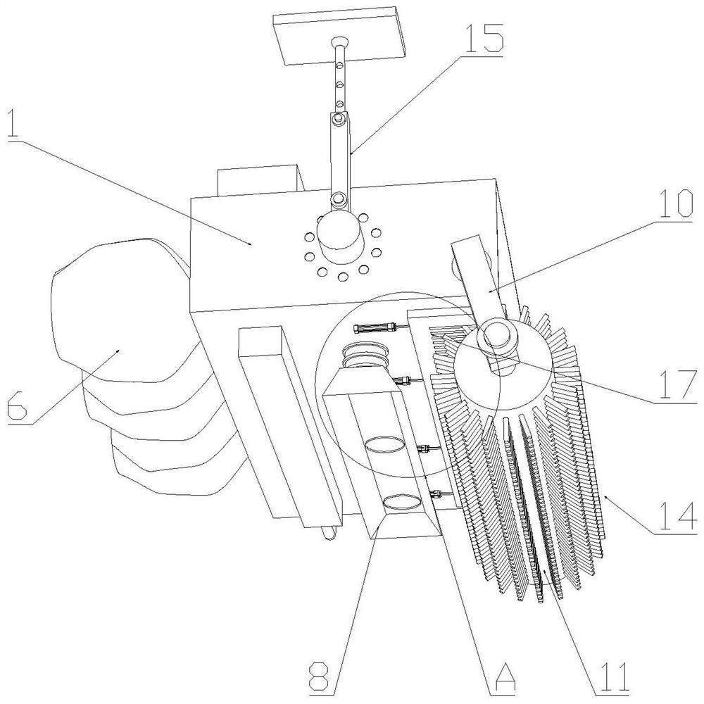
[0038] Such as Figure 7As shown, on the basis of the above-mentioned embodiments, the dust removal box 1 in this embodiment is provided with a mounting assembly 15; the mounting assembly 15 includes a connecting seat 26, a mounting rod 28, a telescopic rod 29 and a mounting plate 32; the connecting seat 26 is rotated and set On the dust removal box 1 ; one end of the installation rod 28 is connected with the connection seat 26 , and the other end is slidably connected with the telescopic rod 29 ; Mounting assembly 15 also comprises threaded rod one 27 and nut one; Dust removal box 1 is provided with a circle of fixing hole one 13 along the periphery of connection seat 26; One end of mounting rod 28 is provided with threaded groove one; Through slot 1 is threadedly matched with mounting rod 28, and snapped into fixed hole 1 13 of corresponding position, and the other end cooperates with nut 1. Mounting assembly 15 also comprises threaded rod two 30 and nut two; The other end ...


PUM


Abstract

The invention relates to the technical field of textile processing, in particular to dust removal equipment for textile processing. The equipment comprises a dust removal box, a mounting frame, a first dust suction fan, a filter plate, a second dust suction fan, a dust collection bag, a dust suction pipe, a dust collection cover, a dust removal assembly and a controller; the mounting frame and the filter plate are arranged in the dust removal box; the first dust collection fan is arranged at the dust inlet end in the dust removal box through the mounting frame; the second dust collection fan is arranged at the dust outlet end of the dust removal box with the filter plate; the dust collection bag is communicated with the second dust collection fan; the dust suction pipe is arranged at the bottom of the dust removal box and communicates with a dust removal chamber and the dust collection cover; and the dust removal assembly is arranged on an opening in the dust inlet end of the dust removal box. A first dust removal part and a second dust removal part are matched, residual textile dust is sucked into the dust removal chamber through the dust collection cover, and the textile dust is filtered by the filter plate and finally enters the dust collection bag. Multiple dust removal modes are arranged, deep and comprehensive dust removal is achieved, the dust removal effect is good, cleaning is convenient, and the dust removal effect is stable.

Description

technical field [0001] The invention relates to the technical field of textile processing, in particular to a dust removal device for textile processing. Background technique [0002] The Chinese patent document with the authorized announcement number CN 212533328 U discloses a device for removing textile dust on textile fabrics, including the overall structure of the dust removal rack, the overall structure of the dust removal rack includes a dust removal rack cross bar, and the two ends of the dust removal rack cross bar Both are equipped with side plates of dust removal racks, and one side of the side plates of the dust removal racks is provided with a dust removal roller limit column and a dust collection box limit block. Structure, the dust removal roller is engaged and fixed between the relative dust removal roller limit posts. However, the existing dust removal equipment for textile processing has a single dust removal method, and the dust removal is not thorough, an...

Claims


Application Information

Patent Timeline
Patent Type & Authority Applications(China)
IPC IPC(8): D06G1/00B01D46/10B01D47/06B01D46/02B01D50/00
CPCD06G1/00B01D46/10B01D47/06B01D46/02
Inventor 凌杰
Owner SSUZHOU KELANBO TEXTILE TECH CO LTD
Why Eureka
Try Eureka