Construction method of passive area enhanced underground diaphragm wall

A technology of underground diaphragm wall and construction method, which is applied in the direction of excavation, artificial island, sheet pile wall, etc., and can solve the problems of large displacement and deformation of underground diaphragm wall, low construction efficiency, and long construction period

Active Publication Date: 2021-12-07
SHANGHAI CONSTRUCTION GROUP
View PDF3 Cites 0 Cited by
  • Summary
  • Abstract
  • Description
  • Claims
  • Application Information

AI Technical Summary

Problems solved by technology

[0004] The present invention improves the conventional underground diaphragm wall based on the "bulging belly" lateral deformation form of the underground diaphragm wall in soft soil foundation pit, and provides a construction method of the passive area enhanced underground diaphragm wall, which breaks through the groove section shape of the conventional underground diaphragm wall , so that the underground diaphragm wall groove section is composed of the enclosure section arranged along the sideline of the foundation pit and the passive area reinforcement section perpendicular to the enclosure section and connected with the enclosure section. The passive area reinforcement section plays the role of reinforcement of the passive area of ​​the foundation pit. The formation of an underground diaphragm wall with its own passive zone reinforcement solves the problems of large displacement and deformation of the underground diaphragm wall in the prior art, as well as many soil disturbances, low construction efficiency and long construction period caused by soil reinforcement in the passive zone of the foundation pit

Method used


Image

  • Construction method of passive area enhanced underground diaphragm wall
  • Construction method of passive area enhanced underground diaphragm wall
  • Construction method of passive area enhanced underground diaphragm wall

Examples


Embodiment Construction

[0035] The present invention will be described in further detail below in conjunction with the accompanying drawings and specific embodiments. The technical content and features of the present invention will be described in detail below by referring to the illustrated embodiments in conjunction with the accompanying drawings. It should be further noted that all the drawings are in very simplified form and use imprecise scales, and are only used to facilitate and clearly assist the purpose of illustrating the embodiments of the present invention. For the convenience of description, the "up" and "down" described below are consistent with the directions of up and down in the drawings, but this should not be a limitation of the technical solution of the present invention.

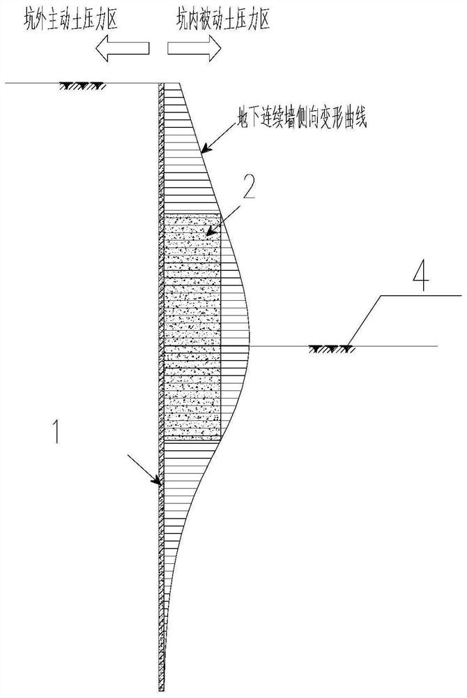
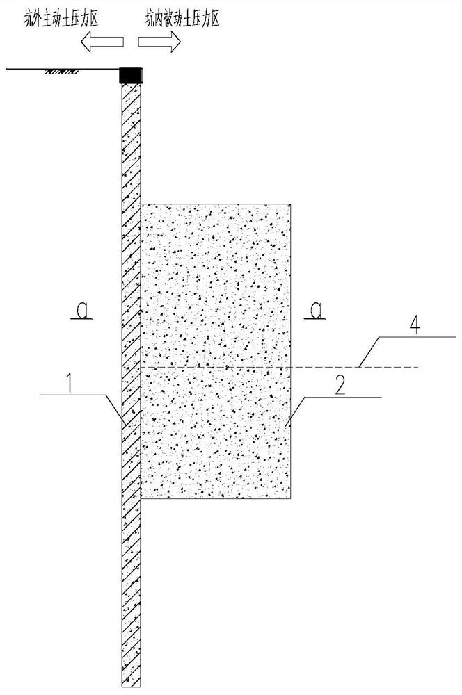
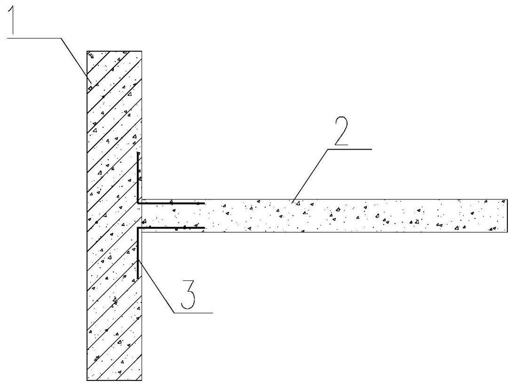
[0036] see Figure 1 to Figure 11 , the present embodiment discloses a construction method of a passive zone enhanced underground diaphragm wall, comprising the following steps:

[0037] Working condition 1: ...


PUM


Abstract

The invention provides a construction method of a passive area reinforced underground diaphragm wall. The construction method comprises the following steps that an underground diaphragm wall is constructed, wherein the underground diaphragm wall comprises an enclosure section and a passive area reinforcing section, the enclosure section is arranged along the side line of a foundation pit, and the passive area reinforcing section is arranged perpendicular to the enclosure section and is connected with the enclosure section; earth is excavated layer by layer from top to bottom, and horizontal supports are constructed layer by layer till a base is excavated; a cushion layer and a foundation bottom plate are poured in the center of the foundation pit; the cushion layer and the foundation bottom plate on the periphery of the foundation pit are poured, when the foundation bottom plate is poured to the passive area reinforcing section of the underground diaphragm wall on the periphery, the passive area reinforcing section above the base is chiseled away, and the cushion layer and the foundation bottom plate on the periphery of the foundation pit are poured in time; and the horizontal supports are dismantled layer by layer from bottom to top, and basement floor slabs are poured layer by layer till the whole basement body is completed. By additionally arranging the passive area reinforcing section, the underground diaphragm wall with the passive area reinforcing function is formed, and the problems that in the foundation pit excavation process, displacement deformation of the underground diaphragm wall is large, disturbance of conventional soil body reinforcing of the passive area in the pit is large, and the construction period is long are solved.

Description

technical field [0001] The invention belongs to the technical field of building construction, and in particular relates to a construction method of a passive zone enhanced underground diaphragm wall. Background technique [0002] For the foundation pit engineering in the soft soil area of ​​Shanghai, a large number of practices have proved that in the foundation pit support structure, the lateral deformation curve of the underground diaphragm wall generally presents a "bulging belly" shape with small ends and a large middle (such as figure 1 shown), that is, the horizontal displacement near the foundation floor of the passive area in the pit is the largest. Based on this deformation form, the practice of conventional foundation pit engineering is to set up passive zone soil reinforcement near the inner base of the foundation pit to reduce the lateral deformation of the enclosure wall. The soil in the passive earth pressure zone is improved and reinforced. However, this rein...

Claims


Application Information

Patent Timeline
Patent Type & Authority Applications(China)
IPC IPC(8): E02D17/02E02D17/04E02D19/18E02D29/045E02D5/18
CPCE02D17/02E02D17/04E02D19/18E02D29/045E02D5/18E02D2250/0023
Inventor 张竹庭钟铮林巧颜超周婉颜正红
Owner SHANGHAI CONSTRUCTION GROUP
Why Eureka
Try Eureka