Geothermal utilization device

A geothermal and heat exchange layer technology, applied in geothermal energy, geothermal energy power generation, geothermal collectors, etc., can solve problems such as blockage of return water flower pipes, and achieve a project with a small footprint, high utilization of geothermal energy, and low construction costs Effect

Pending Publication Date: 2021-12-07
张景明
View PDF0 Cites 2 Cited by
  • Summary
  • Abstract
  • Description
  • Claims
  • Application Information

AI Technical Summary

Problems solved by technology

The functions of the intake well and the return well alternate in a certain time interval, which solves the problem of blockage of the return water flower pipe

Method used


Image

  • Geothermal utilization device
  • Geothermal utilization device
  • Geothermal utilization device

Examples


Embodiment Construction

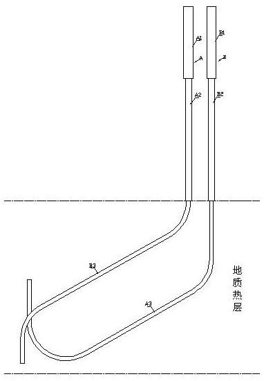
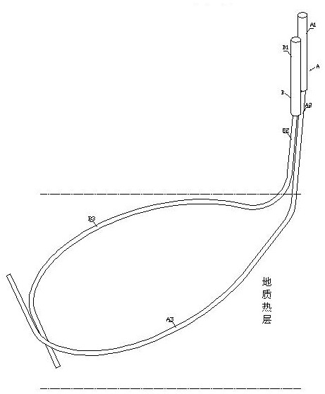
[0021] As shown in the figure, a geothermal utilization device includes water intake well A and return well B. Water intake well A includes deep well pump layer IA1, bare pipe layer IA2 and heat exchange layer IA3, and return well B includes deep well pump layer IIB1, bare pipe layer Layer IIB2 and heat exchange layer IIB3, heat exchange layer IA3 and heat exchange layer IIB3 are flower tubes, and heat exchange layer IA3 and heat exchange layer IIB3 enter the geothermal layer and change direction through the first bending and move away from water intake well A and The center direction of the backwater well B extends, the distance between the heat exchange layer IA3 and the heat exchange layer IIB3 is much greater than the distance between the light pipe layer IA2 and the light pipe layer IIB2, and the heat exchange layer IA3 and the heat exchange layer IIB3 make Their tails meet at close range.

[0022] The light pipe layer IA2 and the light pipe layer IIB2 are vertically para...


PUM


Abstract

The invention discloses a geothermal utilization device. The geothermal utilization device comprises a water intake well and a water return well, the water intake well comprises a deep well pump layer I, a light pipe layer I and a heat exchange layer I, the water return well comprises a deep well pump layer II, a light pipe layer II and a heat exchange layer II, the heat exchange layer I and the heat exchange layer II are perforated pipes, after entering a geological heat layer, the heat exchange layer I and the heat exchange layer II simultaneously extend in the direction away from the centers of the water intake well and the water return well after being bent and turned for the first time, the distance between the heat exchange layer I and the heat exchange layer II is far larger than the distance between the light pipe layer I and the light pipe layer II, and the tails of the heat exchange layer I and the heat exchange layer II closely intersect with each other through secondary turning. Compared with the prior art, the geothermal utilization device has the advantages that regular exchange of pumping and returning is realized, and the problem of return water blockage can be solved; all pumping wells and return water wells are centrally arranged on the ground, underground heat collection is radially arranged, the heat collection area is large, the engineering floor area is small, and the construction cost is low; and each group of heat collecting perforated pipes are stereoscopically arranged in the geological heat layer, so that the geothermal utilization rate is high.

Description

technical field [0001] The invention relates to a geothermal utilization device. Background technique [0002] At present, there are two modes of geothermal exploitation in the prior art: the first mode is the mode of one pumping and two circuits. Although this mode has a high thermal utilization rate, it has the following two disadvantages: the first is that it occupies a large area of ​​the ground, and the construction The cost is high, and the second is that the flower pipe of the backwater well is easy to block after a long time. The second mode is U-shaped heat exchanger for underground heat exchange. The disadvantage of this method is that the heat exchange area is small (caused by construction personnel), and it is not suitable for large-scale heating projects. Therefore, it is a technical problem to be solved at present to design a geothermal utilization device that occupies a small ground area and is not suitable for blockage of the return water flower pipe. Cont...

Claims


Application Information

Patent Timeline
Patent Type & Authority Applications(China)
IPC IPC(8): F24T10/13F24T10/20
CPCF24T10/13F24T10/20F24T2010/50Y02E10/10
Inventor 张景明
Owner 张景明
Why Eureka
Try Eureka