Visual recognition device based on three-dimensional simulation

A technology of visual recognition and three-dimensional simulation, which is applied to devices for catching or killing insects, TVs, color TVs, etc. It can solve the problems of attracting flying insects, affecting inspection results, and easy blurring of imaging, so as to reduce line of sight obstruction and facilitate Effect of using, reducing impact

Pending Publication Date: 2021-12-07
QUJING POWER SUPPLY BUREAU YUNNAN POWER GRID CO LTD
View PDF0 Cites 0 Cited by
  • Summary
  • Abstract
  • Description
  • Claims
  • Application Information

AI Technical Summary

Problems solved by technology

[0003] The traditional campus inspection is carried out manually. Due to the labor-intensive characteristics of manual inspection, a method of automatic inspection is created by combining the inspection platform, inspection robot and intelligent analysis service platform. Points are created through the inspection platform and the point information is synchronized to the inspection robot and the intelligent analysis service platform, and the point information scene is captured by the inspection robot, and the intelligent analysis service platform detects the captured image according to the inspection robot, and obtains Inspection results
[0004] During the use of the existing inspection vehicle, no corresponding rain-shielding device is installed, so that when the inspection vehicle works in rainy days, the identification equipment is exposed to rainwater for a long time, and the mirror is easy to attach too much raindrops, which makes the identification equipment The line of sight is obstructed, and the transmitted image is easily blurred, which will affect the inspection of the inspection vehicle, and generally there are many green plants on the campus. The line of sight of the recognition equipment is obstructed, which is likely to cause blurred images captured by the monitoring end and affect the inspection results. In view of the above situation, we propose a visual recognition device based on 3D simulation

Method used


Image

  • Visual recognition device based on three-dimensional simulation
  • Visual recognition device based on three-dimensional simulation
  • Visual recognition device based on three-dimensional simulation

Examples


Embodiment 1

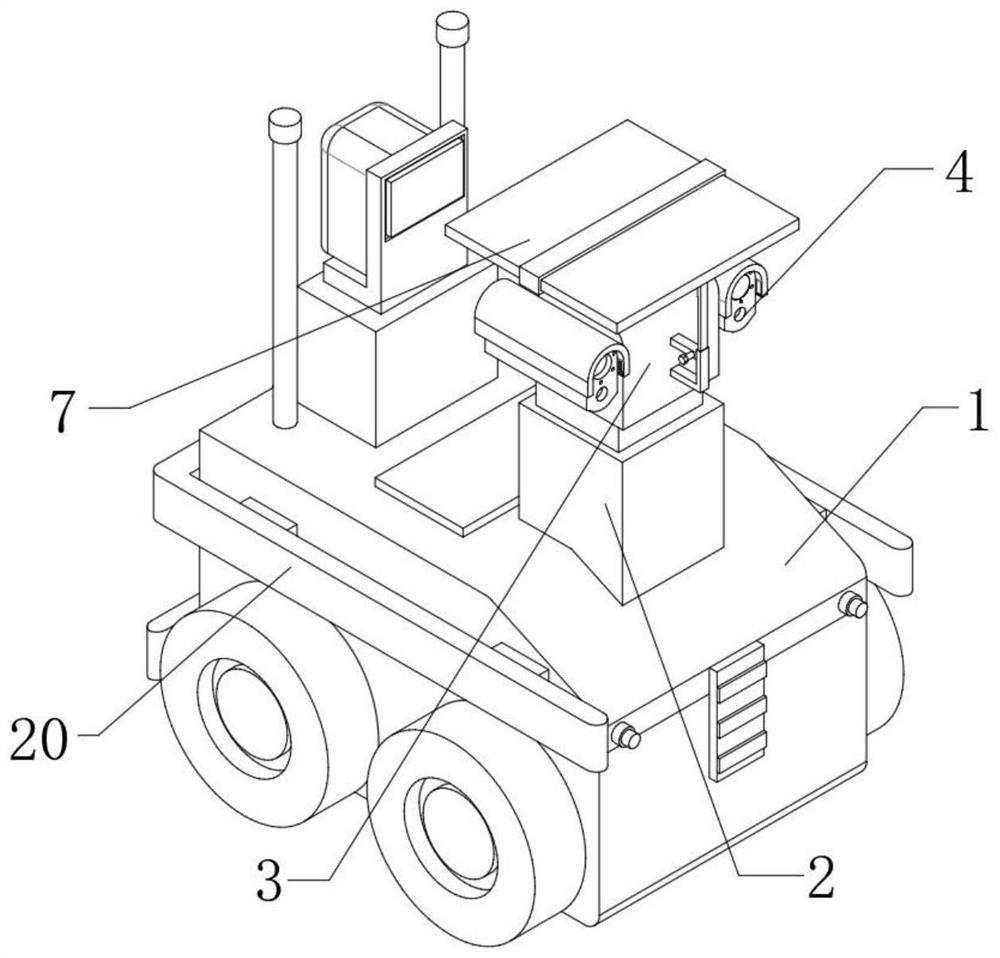
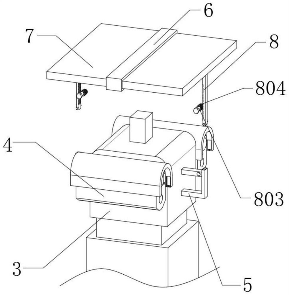
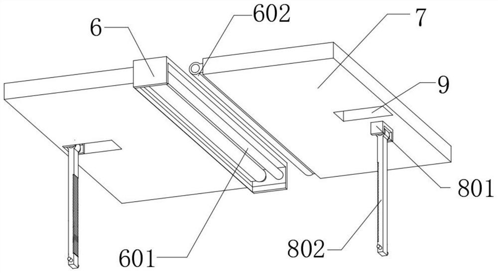
[0042] Such as Figure 1-9 As shown based on the three-dimensional simulation visual recognition device, the inspection vehicle 1 and the upper surface of the digital pan / tilt 3 are equipped with a fixed plate 6, the inner rotation of the fixed plate 6 is connected with a connecting rod 601, and the outer surface of the connecting rod 601 is fixedly sleeved with a sleeve The plate 602 and one end of the sleeve plate 602 are fixedly mounted with a baffle 7 , and a chute 9 is provided on the lower surface of the baffle 7 .

[0043] An adjustment mechanism 8, the adjustment mechanism 8 is installed between the support seat 5 and the baffle 7, the baffle 7 is connected to the upper end of the identification device 4 through the adjustment mechanism 8, the adjustment mechanism 8 includes a tooth plate 802, and the tooth plate 802 is assembled on the baffle 7, one end of the tooth plate 802 is slidably connected to the inside of the support seat 5, and the adjustment mechanism 8 als...

Embodiment 2

[0047] Such as Figure 1-9 Based on the three-dimensional simulation visual recognition device shown, the outer surface of the recognition device 4 is equipped with a casing 10, and the inside of the casing 10 is provided with a connecting groove 11, and the inside of the connecting groove 11 is equipped with an insect trap lamp 12, and one side of the insect trap lamp 12 is fixed. U-shaped seat 13 is installed, and the inside of U-shaped seat 13 is fixedly equipped with protective net 16, and protective net 16 is equipped with grid 17 away from the side of insect trap lamp 12, and a side of grid 17 is equipped with cleaning mechanism 14.

[0048] The cleaning mechanism 14 includes a scraper 141, a guide block 142 and a steel cable 143. One side of the grid 17 is slidably connected with a scraper 141, and both ends of the scraper 141 are fixedly equipped with a guide block 142, and the guide block 142 is slidably connected to a U-shaped In the inside of seat 13, one end of ste...

Embodiment 3

[0053] Such as Figure 1-9 Based on the three-dimensional simulation visual recognition device shown, the upper surface of the inspection vehicle 1 is fixedly installed with a fixed seat 2, and the upper surface of the fixed seat 2 is rotatably connected to a digital pan-tilt 3, and one side of the digital pan-tilt 3 is fixedly installed with a support seat 5 The two sides of the digital pan / tilt 3 are equipped with identification equipment 4, the upper end of the identification equipment 4 is equipped with a baffle plate 7, the interior of the inspection vehicle 1 is fixedly installed with a connecting cylinder 22, and the internal movable sleeve of the connecting cylinder 22 is connected with a telescopic spring 23 A moving block 21 is movably plugged into the connecting cylinder 22 , and a protective plate 20 is fixedly installed on the end of the moving block 21 away from the telescopic spring 23 .

[0054] When the inspection vehicle 1 is collided during the inspection pr...


PUM


Abstract

The invention discloses a visual recognition device based on three-dimensional simulation, and relates to the technical field of recognition devices. The device comprises an inspection vehicle, the upper surface of the inspection vehicle is fixedly provided with a fixed seat, the upper surface of the fixed seat is rotatably connected with a digital holder, two sides of the digital holder are provided with recognition devices, and the upper ends of the recognition devices are provided with baffle plates. When the three-dimensional simulation visual recognition device is used and polled in rainy days, a threaded rod is rotated, so that a gear on the outer surface of the threaded rod drives a toothed plate to move up and down, the inclination of a baffle plate is adjusted, the periphery of identification equipment is shielded, and the inclined baffle plate prevents rainwater from being splashed on a lens of the identification equipment, therefore, the lens is prevented from being dropped by raindrops, images captured by the monitoring end are prevented from being blurred, and normal and safe inspection of the inspection vehicle is not affected.

Description

technical field [0001] The invention relates to the technical field of recognition devices, in particular to a three-dimensional simulation-based visual recognition device. Background technique [0002] Three-dimensional simulation refers to a realistic virtual environment generated by computer technology, with multiple perceptions such as sight, hearing, touch, and taste. Users can use various sensing devices to interact with entities in the virtual environment through their natural skills. One technology, visual recognition, is to use machines instead of human eyes to make measurements and judgments. [0003] The traditional campus inspection is carried out manually. Due to the labor-intensive characteristics of manual inspection, a method of automatic inspection is created by combining the inspection platform, inspection robot and intelligent analysis service platform. Points are created through the inspection platform and the point information is synchronized to the ins...

Claims


Application Information

Patent Timeline
Patent Type & Authority Applications(China)
IPC IPC(8): G07C1/20H04N5/225H04N7/18A01M1/04A01M1/22F16F15/067F16M11/42
CPCG07C1/20H04N7/185A01M1/04A01M1/223F16M11/42F16F15/067H04N23/51
Inventor 刘东省郑杰周磊邹茂青赵承刚
Owner QUJING POWER SUPPLY BUREAU YUNNAN POWER GRID CO LTD
Why Eureka
Try Eureka