
Base station hardware detection method and device

A detection method and hardware technology, applied in the field of communications, can solve problems such as time-consuming and labor costs, low hardware failure efficiency, and inability to feedback hardware and hardware status information from base station management tools, so as to improve the success rate and efficiency and improve efficiency. Effect

Active Publication Date: 2021-12-07
DATANG MOBILE COMM EQUIP CO LTD
View PDF5 Cites 0 Cited by
  • Summary
  • Abstract
  • Description
  • Claims
  • Application Information

AI Technical Summary

Problems solved by technology

However, this solution can only receive the hardware status information corresponding to the hardware fed back by the alarm module after the alarm module has alarmed the target hardware, so as to determine whether the hardware is faulty. When the alarm module does not alarm the target hardware, The alarm module cannot find the hardware state information corresponding to the hardware, and cannot feed back the hardware state information corresponding to the hardware to the base station management tool, resulting in low efficiency in finding hardware faults
[0005] Another solution is: in the base station management tool, according to the target hardware information, determine the target node in the MIB (ManagementInformation Base, Information Management Base), and inquire one by one in many lists corresponding to the target node hardware information of the target hardware, and obtain the hardware state information of the target hardware to determine whether the target hardware is faulty, especially when it is necessary to search the hardware state information of multiple target hardware for hardware fault judgment, the above-mentioned solution of the scheme The search process will consume a lot of time and labor costs, seriously affecting the efficiency of finding hardware faults

Method used


Image

  • Base station hardware detection method and device
  • Base station hardware detection method and device
  • Base station hardware detection method and device

Examples


Embodiment 1

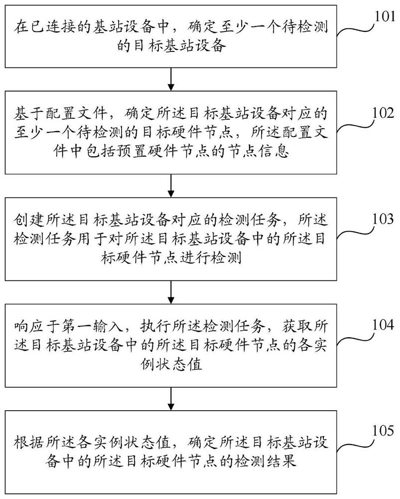
[0027] refer to figure 1 , showing a flow chart of an embodiment of a base station hardware detection method of the present invention, which is applied to a base station management platform, and may specifically include:

[0028] Step 101, among the connected base station devices, determine at least one target base station device to be detected;

[0029] Step 102: Determine at least one target hardware node to be detected corresponding to the target base station device based on a configuration file, where the configuration file includes node information of preset hardware nodes;

[0030] Step 103, creating a detection task corresponding to the target base station device, where the detection task is used to detect the target hardware node in the target base station device;

[0031] Step 104, in response to the first input, execute the detection task, and acquire the status values ​​of each instance of the target hardware node in the target base station device;


PUM


Abstract

The embodiment of the invention provides a base station hardware detection method and device which are applied to a base station management platform, and the method comprises the steps of determining at least one target base station device to be detected in connected base station devices; based on a configuration file, determining at least one to-be-detected target hardware node corresponding to the target base station device, the configuration file comprising node information of a preset hardware node; creating a detection task corresponding to the target base station equipment, wherein the detection task is used for detecting the target hardware node in the target base station equipment; in response to a first input, executing the detection task, and obtaining each instance state value of the target hardware node in the target base station equipment; and determining a detection result of the target hardware node in the target base station equipment according to each instance state value. According to the embodiment of the invention, the detection task can be customized, so that the hardware detection efficiency is improved and a large amount of cost is saved.

Description

technical field [0001] The present invention relates to the technical field of communications, in particular to a base station hardware detection method and device. Background technique [0002] With the rapid development of wireless communication technology, telecom operators at home and abroad have deployed a large number of base station equipment. As the interface equipment for mobile devices to access the Internet, the base station is composed of a large number of hardware. During the operation of the base station, hardware resources may fail, affecting the performance of the base station. Therefore, during the operation of the base station, it is necessary to find hardware faults in time to ensure the operation performance of the base station. [0003] In the prior art, the following two schemes are used to search for hardware faults: [0004] One solution is to determine whether there is a certain type of hardware failure in the base station through an alarm module i...

Claims


Application Information

Patent Timeline
Patent Type & Authority Applications(China)
IPC IPC(8): H04W24/00G01K13/00
CPCH04W24/00G01K13/00Y02D30/70
Inventor 楚立君
Owner DATANG MOBILE COMM EQUIP CO LTD
Learn More