Turnover bed

A technology of turning over bed and bed board, which is applied in the field of turning bed, can solve the problems of difficulty in turning over a patient, and it is difficult for a patient to turn over, and achieves the effect of a simple and reasonable overall structure.

Pending Publication Date: 2021-12-10
洪福景
View PDF10 Cites 0 Cited by
  • Summary
  • Abstract
  • Description
  • Claims
  • Application Information

AI Technical Summary

Problems solved by technology

[0002] It is difficult to turn over the paralyzed patients, especially most of the paralyzed patients are women or the elderly, because of their weak strength, it is difficult to turn over the patients
However, patients who are paralyzed in bed need to turn over frequently, because if the same part of the patient is compressed for a long time, it will gradually become necrotic

Method used


Image

  • Turnover bed
  • Turnover bed
  • Turnover bed

Examples


Embodiment 1

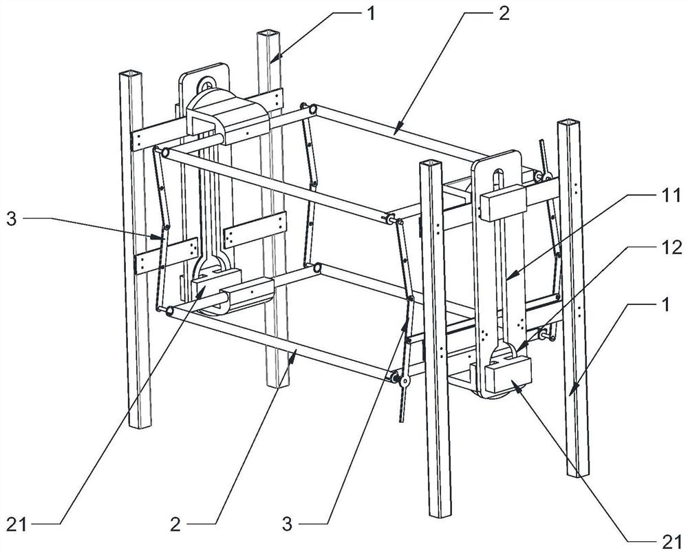
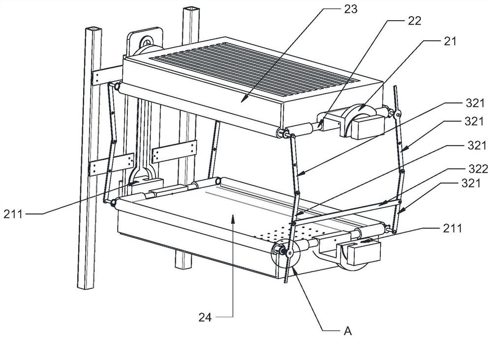
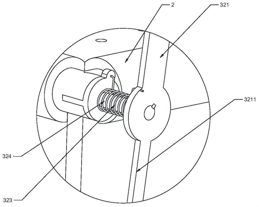
[0037] Such as Figure 1 to Figure 4 As shown, the present embodiment discloses a turning bed, including two bed heads 1, two bed boards 2 and a guide structure 3; the bed head 1 is provided with a vertical straight rail 11, and the bottom of the straight rail 11 is provided with A circular revolving rail 12; the two ends of the bed board 2 are fixed with sliding parts 21 adapted to the straight rail 11 and the revolving rail 12, and the sliding part 21 is installed on the straight rail 11 or the revolving rail 12, the two ends of the bed board 2 are respectively connected to the two headboards 1 by the sliders 21; the bed board 2 is provided with a recessed area; The recessed area formed by deformation; in order to avoid causing suffocation, the bottom of the recessed area is also set as a breathable structure; the two bed boards 2 are connected by the guide structure 3, and the guide structure 3 is used to maintain the two bed boards. The bed boards 2 are mirror images of e...

Embodiment 2

[0047] Such as Figure 5 with Image 6 As shown, the present embodiment discloses a turning bed, including two bed heads 1, two bed boards 2 and a guide structure 3; the bed head 1 is provided with a vertical straight rail 11, and the bottom of the straight rail 11 is provided with A circular revolving rail 12; the two ends of the bed board 2 are fixed with sliding parts 21 adapted to the straight rail 11 and the revolving rail 12, and the sliding part 21 is installed on the straight rail 11 or the revolving rail 12, the two ends of the bed board 2 are respectively connected to the two headboards 1 by the sliders 21; the bed board 2 is provided with a recessed area; The recessed area formed by deformation; in order to avoid causing suffocation, the bottom of the recessed area is also set as a breathable structure; the two bed boards 2 are connected by the guide structure 3, and the guide structure 3 is used to maintain the two bed boards. The bed boards 2 are mirror images o...


PUM


Abstract

The invention discloses a turnover bed. The turnover bed comprises two bed heads, two bed plates and guide structures, wherein longitudinal straight rails are arranged on the bed heads, and circular rotating rails are arranged at the bottoms of the straight rails; sliding pieces matched with the straight rails and the rotating rails are fixed at the two ends of each bed plate, and the sliding pieces are mounted in the straight rails or the rotating rails, so that the two ends of each bed plate are connected to the two bed heads through the sliding pieces respectively; a concave area is arranged on each bed plate; the concave area comprises a concave area body which is in a concave state or is formed through elastic deformation; in order to avoid suffocation, the bottom of the concave area is further provided with a breathable structure; and the two bed plates are connected through the guide structures, the guide structures are used for maintaining the two bed plates to be in a mirror image state, and the mirror image datum plane of the guide structures is parallel to the bed plates. The paralyzed patient in bed can turn over by folding and rotating the two bed plates.

Description

technical field [0001] The invention relates to the technical field of beds, in particular to a turning bed. Background technique [0002] It is more difficult to turn over for the paralyzed patient in bed, especially most of the patients who take care of the paralyzed in bed are women or old people, because their strength is small, so it is difficult to turn over for the patient. However, patients who are paralyzed in bed need to turn over frequently, because if the same part of the patient is compressed for a long time, it will gradually become necrotic. Contents of the invention [0003] The purpose of the present invention is to provide a turning bed which is convenient for patients to turn over. [0004] The invention provides a turning bed, which includes two bed heads, two bed boards and a guide structure; [0005] The head of the bed is provided with a vertical straight rail, and the bottom of the straight rail is provided with a circular revolving rail; [0006...

Claims


Application Information

Patent Timeline
Patent Type & Authority Applications(China)
IPC IPC(8): A61G7/00A61G7/05
CPCA61G7/001A61G7/05
Inventor 洪福景
Owner 洪福景
Why Eureka
Try Eureka