
Brake iron shoe welding station

A welding station, iron shoe technology, applied in welding equipment, welding equipment, auxiliary welding equipment, etc., can solve the problems of low degree of automation and low work efficiency, and achieve the effect of high degree of automation and improved production efficiency

Inactive Publication Date: 2021-12-10
兴意金工科技(浙江)有限公司
View PDF0 Cites 4 Cited by
  • Summary
  • Abstract
  • Description
  • Claims
  • Application Information

AI Technical Summary

Problems solved by technology

The existing brake shoe welding machines are all welded by a single piece of equipment, which has low work efficiency, and requires workers to take and unload materials, and the degree of automation is low

Method used


Image

  • Brake iron shoe welding station
  • Brake iron shoe welding station
  • Brake iron shoe welding station

Examples


Embodiment Construction

[0033] The following are specific embodiments of the present invention and in conjunction with the accompanying drawings, the technical solutions of the present invention are further described, but the present invention is not limited to these embodiments.

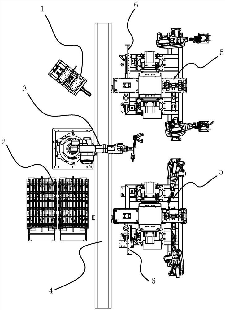
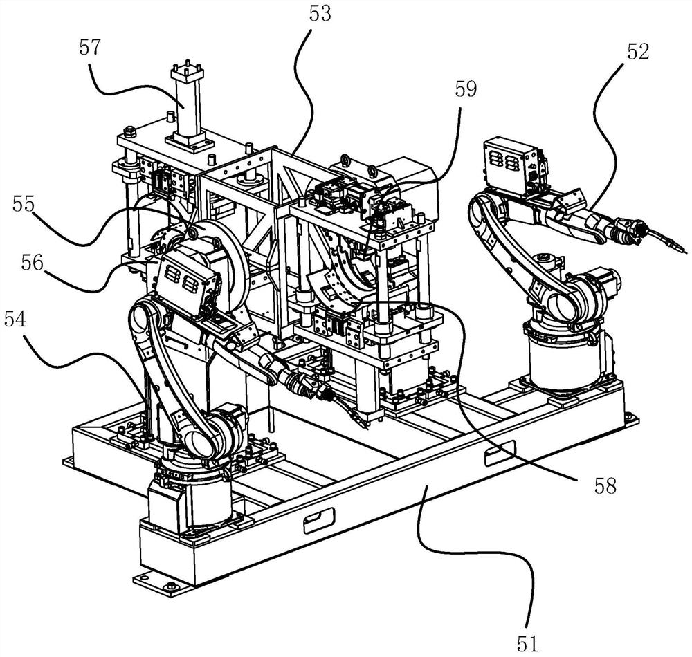
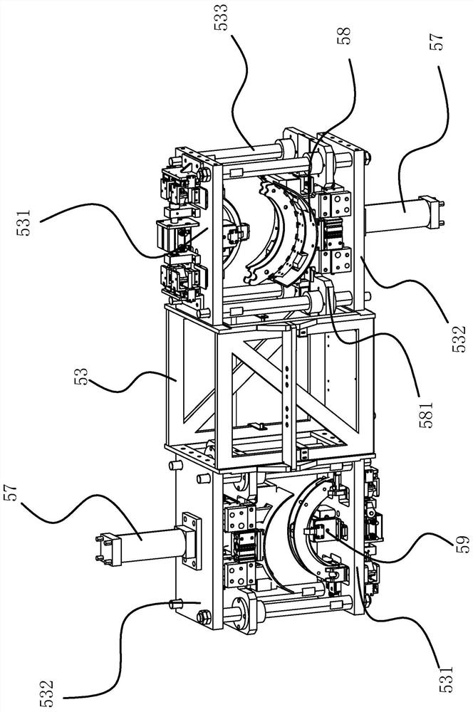
[0034] This brake shoe welding station includes panel feeding tooling (1), rib plate storage rack (2), feeding manipulator (3) capable of grabbing rib plate and panel and sending them to the welding mechanism (5), conveyor belt (4) 1. A welding mechanism (5) for welding the panel and rib plate together, and an unloading tool (6) for taking out the welded brake shoe from the welding mechanism (5) and placing it on the conveyor belt (4). The panel loading tooling (1) and rib storage rack (2) are located on one side of the conveyor belt (4), the unloading tooling (6) and the welding mechanism (5) are located on the other side of the conveyor belt (4), and the feeding manipulator (3 ) is located between the panel loading tooli...


PUM


Abstract

The invention discloses a brake iron shoe welding station. The brake iron shoe welding station comprises a panel feeding tool, a rib plate storage frame, a feeding mechanical arm capable of grabbing a rib plate and a panel and conveying the rib plate and the panel to a welding mechanism, a conveying belt, the welding mechanism for welding the panel and the rib plate together, and a discharging tool for taking out a welded brake iron shoe from the welding mechanism and placing the brake iron shoe on the conveying belt, the panel feeding tool and the rib plate storage frame are located on one side of the conveying belt, the discharging tool and the welding mechanism are located on the other side of the conveying belt, and the feeding mechanical arm is located between the panel feeding tool and the rib plate storage frame. The brake iron shoe welding station can automatically grab materials, automatically unload and convey the materials, is high in automation degree, and greatly improves the production efficiency.

Description

technical field [0001] The invention belongs to the technical field of brake shoe welding, and relates to a brake shoe welding station. Background technique [0002] The brake shoe refers to the brake accessory that is pushed outward by the action of the brake cam or push rod, and presses the brake drum to play a braking role. It is installed on the brake drum and is a key safety part in the automobile braking system. One of the components. The brake shoe includes an arc-shaped rib plate and a steel sheet panel, and two parallel arc-shaped rib plates are vertically welded on the inside of the arc-shaped rib plate. Existing brake shoe welding machines are all welded by a single piece of equipment, which has low work efficiency, and requires workers to take and unload materials, and the degree of automation is low. Contents of the invention [0003] The purpose of the present invention is to solve the above problems in the existing technology, and propose a brake shoe weld...

Claims


Application Information

Patent Timeline
Patent Type & Authority Applications(China)
IPC IPC(8): B23K31/02B23K37/00B23K37/047B25H3/04
CPCB23K31/02B23K37/047B23K37/00B25H3/04
Inventor 余双成方炜栋梁帆锋毛淑毅
Owner 兴意金工科技(浙江)有限公司
Learn More