Combined groove structure for processing wiredrawing batten

A wire drawing board and combined groove technology, applied in metal processing equipment, manufacturing tools, grinding slides, etc., can solve the problem that the channel steel is not easy to clean, and achieve the effect of easy disassembly, maintenance and cleaning, avoiding rockers, and simple structure.

Pending Publication Date: 2021-12-10
天津优视津阳金属材料有限公司
View PDF0 Cites 0 Cited by
  • Summary
  • Abstract
  • Description
  • Claims
  • Application Information

AI Technical Summary

Problems solved by technology

[0004] During the wire drawing process of the slats, at present, a channel steel through which the slats can pass is set on the workbench, and a drawing disc is set in the channel steel. Since the opening of the channel steel is facing upward and is blocked by the drawing disc, the channel steel is not easy to carry out. to clean up

Method used


Image

  • Combined groove structure for processing wiredrawing batten
  • Combined groove structure for processing wiredrawing batten

Examples


Embodiment Construction

[0026] Below, the present invention is described in detail with reference to accompanying drawing and embodiment:

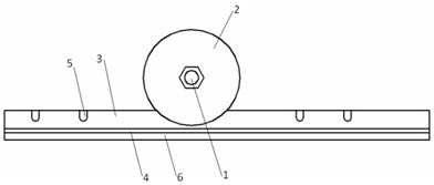
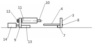
[0027] Such as Figure 1~2 As shown, a combined groove structure processed by drawing laths includes a fixed vertical plate 3, a transverse groove plate 4 is arranged on the side wall of the fixed vertical plate 3, and a horizontal groove plate 4 is arranged on the outside of the horizontal groove plate 4 facing or away from the fixed vertical plate. The movable vertical plate 9 that the plate 3 moves, the inner wall of the fixed vertical plate 3, the inner wall of the mobile vertical plate 9, and the upper end of the transverse groove plate 4 form a groove through which the slats can pass, and a rotating shaft 1 is arranged above the groove. The rotating shaft 1 is provided with a wire drawing disc 2, and the wire drawing disc 2 enters into the groove to perform wire drawing operation on the slats.

[0028] A limit nut is arranged on the rotating shaft 1, and t...


PUM


Abstract

The invention discloses a combined groove structure for processing a wiredrawing batten. The structure comprises a fixed vertical plate, a transverse groove plate is arranged on the side wall of the fixed vertical plate, and a movable vertical plate moving towards or away from the fixed vertical plate is arranged at the outer side of the transverse groove plate. The inner wall of the fixed vertical plate, the inner wall of the movable vertical plate and the upper end of the transverse groove plate are enclosed to form a groove through which the batten can pass, a rotating shaft is arranged above the groove, a wire drawing disc is arranged on the rotating shaft, and the wire drawing disc enters the groove to perform wire drawing operation on the batten. The groove is defined by the fixed vertical plate, the movable vertical plate and the transverse groove plate, the batten is pulled through the groove, disassembly, maintenance and cleaning can be facilitated through the combined groove form, the situation that positioning needs to be conducted again after the wire drawing disc is disassembled is avoided, a supporting shaft is arranged in the movable vertical plate, a sleeve roller is installed, therefore the pulling plate is pressed, plate warping is avoided, and the structure disclosed by the invention is simple and convenient to maintain.

Description

technical field [0001] The invention belongs to the field of plate wire drawing, and in particular relates to a combined groove structure for wire drawing lath processing. Background technique [0002] The wire drawing process is a surface treatment process of metal products. Its principle is to rub the corresponding wire drawing lines on the metal surface through mechanical friction. Improve the overall sense of the product and enhance the overall texture of the product. [0003] Drawing generally has the following effects: straight silk pattern, snow pattern, nylon pattern. At present, most metal wire drawing machines are directly purchased for plate processing. However, there are many problems in the use of the current wire drawing machines. [0004] During the wire drawing process of the slats, at present, a channel steel through which the slats can pass is set on the workbench, and a drawing disc is set in the channel steel. Since the opening of the channel steel is f...

Claims


Application Information

Patent Timeline
Patent Type & Authority Applications(China)
IPC IPC(8): B24B19/00B24B41/02B24B41/06B24B47/00
CPCB24B19/00B24B41/02B24B41/06B24B47/00
Inventor 张仕建
Owner 天津优视津阳金属材料有限公司
Why Eureka
Try Eureka