
Printed matter die cutting device

A printing and die-cutting technology, which is applied in metal processing and other directions, can solve the problem of inconvenient adjustment and cleaning of the cleaning roller, and achieve the effect of avoiding incomplete cleaning

Pending Publication Date: 2021-12-10
无锡市春阳印刷包装有限公司
View PDF0 Cites 0 Cited by
  • Summary
  • Abstract
  • Description
  • Claims
  • Application Information

AI Technical Summary

Problems solved by technology

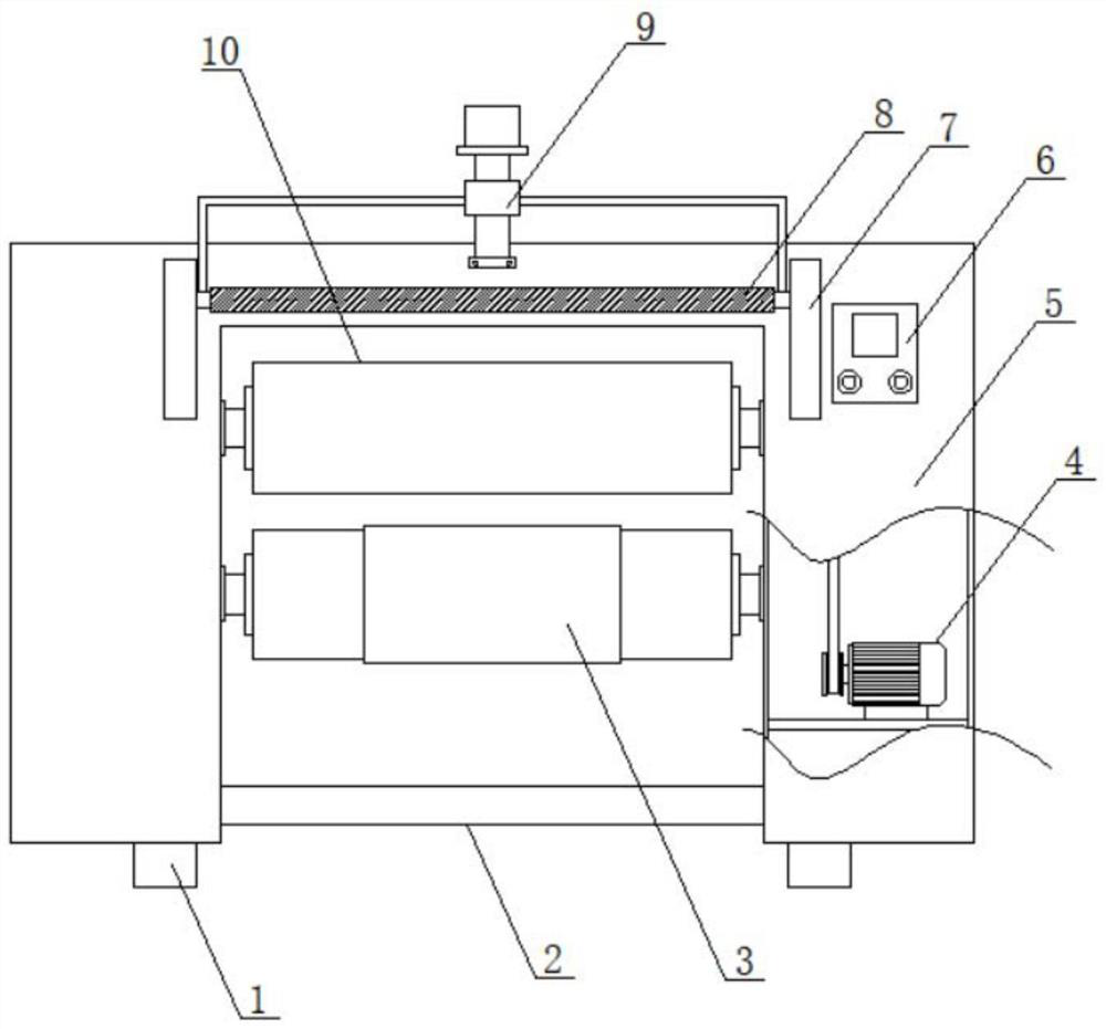
[0004] The object of the present invention is to provide a printed matter die-cutting device to solve the problem that the cleaning roller of the existing printed matter die-cutting device proposed in the above-mentioned background technology is inconvenient to adjust and clean

Method used


Image

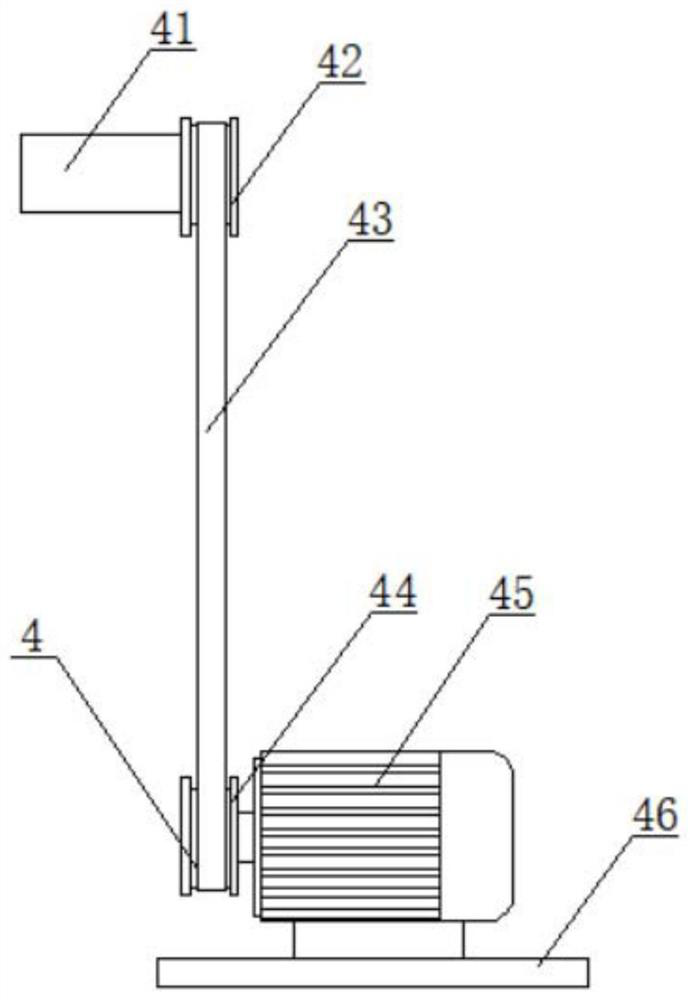
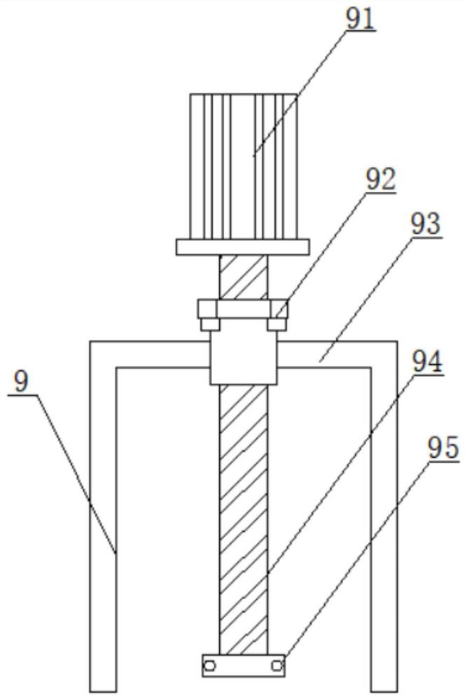
  • Printed matter die cutting device
  • Printed matter die cutting device
  • Printed matter die cutting device

Examples


Embodiment Construction

[0018] The following will clearly and completely describe the technical solutions in the embodiments of the present invention with reference to the accompanying drawings in the embodiments of the present invention. Obviously, the described embodiments are only some, not all, embodiments of the present invention. Based on the embodiments of the present invention, all other embodiments obtained by persons of ordinary skill in the art without making creative efforts belong to the protection scope of the present invention.

[0019] see Figure 1-3 , the present invention provides a technical solution: a printed matter die-cutting device, including a chassis 5 and a foot 1, a foot 1 is provided on the left and right sides of the lower end of the chassis 5, the chassis 5 and the foot 1 are fixedly connected by bolts, the front end of the chassis 5 is right A controller 6 is provided on the side, and the controller 6 is electrically connected to the power supply. A transmission mecha...


PUM


Abstract

The invention discloses a printed matter die cutting device which comprises a machine box and foot pads, wherein one foot pad is arranged on each of the left side and the right side of the lower end of the machine box, the machine box is fixedly connected with the foot pads through bolts, a controller is arranged on the right side of the front end of the machine box and electrically connected with a power source, and a transmission mechanism is arranged at the right end in the machine box. For the printed matter die cutting device disclosed by the invention, by changing a traditional manual adjustment mode into an existing mode of connection transmission through a lead screw and a sleeve, in this way, adjustment can be more convenient and faster, and different heights of the two sides cannot occur during adjustment. When the printed matter die cutting device is used for cleaning, at this time, a second motor rotates to drive the lead screw to rotate and can rotate forwards and backwards, so that the sleeve can move up and down, a bracket can be driven to move, a cleaning roller can move, the left end and the right end of the cleaning roller are the same in elevation, cleaning can be more thorough, and residues are avoided.

Description

technical field [0001] The invention belongs to the related technical field of mechanical equipment, and in particular relates to a die-cutting device for printed matter. Background technique [0002] Die-cutting machine is also called beer machine, cutting machine, CNC punching machine, mainly used for die-cutting, indentation and bronzing of some non-metallic materials, stickers, EVA, double-sided tape, electronics, mobile phone rubber pads, etc. Operation, lamination, automatic waste discharge, die cutting machine uses steel knife, metal mold, steel wire, exerts a certain pressure through the embossing plate, and cuts the printed matter or cardboard into a certain shape. [0003] The existing printed matter die-cutting device has the following problems: the existing printed matter die-cutting device generally controls the impurities on the rubber roller manually, which is inconvenient and quick to clean up, and there may be left and right height adjustments Not the same ...

Claims


Application Information

Patent Timeline
IPC IPC(8): B26F1/38B26D7/08
CPCB26F1/384B26D7/088
Inventor 华曙
Owner 无锡市春阳印刷包装有限公司
Learn More