Pneumatic tire for electric two-wheeled vehicle
A technology of pneumatic tires and electric two-wheels, which is applied to bicycle tires, motor vehicles, tire parts, etc., to improve the anti-skid performance of wet land and ensure the effect of continuity
- Summary
- Abstract
- Description
- Claims
- Application Information
AI Technical Summary
Problems solved by technology
Method used
Image

Examples
Embodiment 1
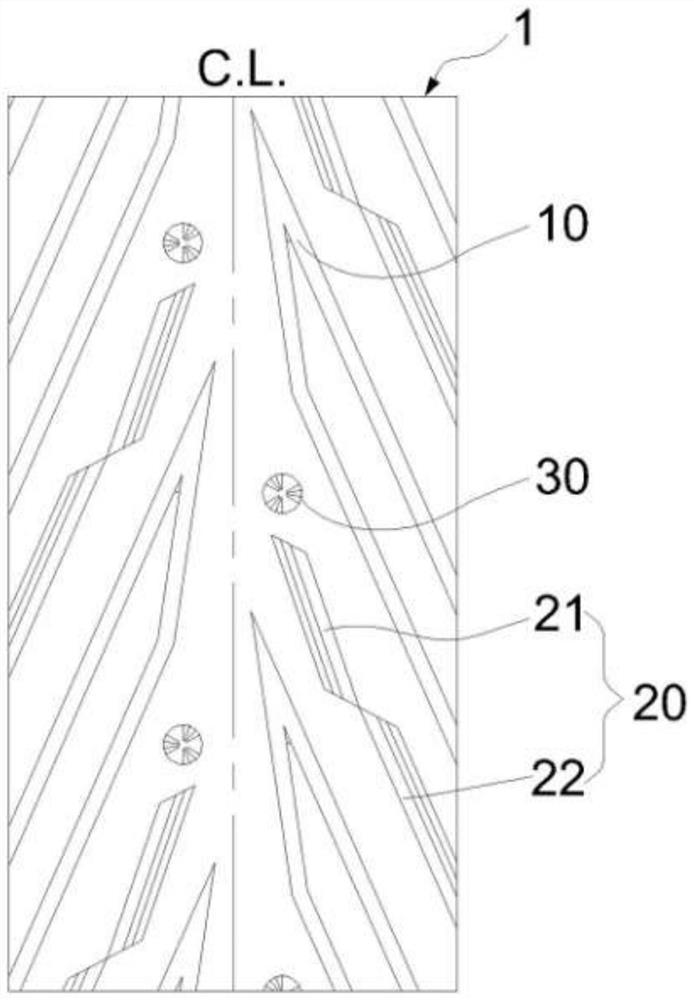
[0032] figure 2 It is a schematic diagram of the tread pattern structure of Embodiment 1 of the present invention. A pneumatic tire for an electric two-wheeled vehicle comprises a tire body, and the tire body includes a tread 1 . Tread patterns are provided on the tread 1 , and the tread patterns on both sides of the tread 1 are symmetrical with respect to the center plane C.L. of the tire and are dislocated along the circumferential direction of the tire. The tread pattern includes a bent main groove 10 , an inclined main groove 20 and a central anti-skid suction cup 30 , and the groove width of the inclined main groove 20 is greater than that of the bent main groove 10 .
[0033] The inclined main grooves 20 are arranged at intervals along the tire circumferential direction, and the bent main grooves 10 are arranged between the circumferentially adjacent inclined main grooves 20 . The bent main groove 10 is composed of two sections of grooves connected to each other, and ...
Embodiment 2
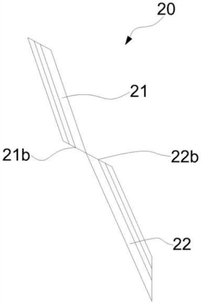
[0037] Such as Figure 6-Figure 7As shown, the difference between this embodiment and Embodiment 1 is that, in this embodiment, in order to further enhance the function of the inclined main groove 20 to prevent stone trapping, the inner groove wall 21a of the upper groove 21 and the inner groove wall 21a of the lower groove 22 The outer groove walls 22a are all set in a stepped shape, which can be set in 2-4 steps. In this embodiment, both the inner side wall 21 a of the upper groove 21 and the outer side wall 22 a of the lower groove 22 are provided with three-step groove walls. The step design of the groove wall can make the cross-sectional width of the groove gradually narrow from the surface to the bottom. Even if the stone enters the surface of the groove, the step can prevent the stone from being further clamped into the bottom of the groove and help the stone to be discharged when the tire is running. The upper groove 21 and the lower groove 22 are diagonally dislocate...
Embodiment 3
[0040] Such as Figure 9-Figure 10 As shown, the difference between this embodiment and Embodiment 1 is that, in this embodiment, in order to further take into account the service life of the central anti-skid suction cup 30 and the rigidity of the tread 1, the depth h1 of the arc disc 30a is set to be inclined mainly 20%-40% of the depth H of the groove 20, and the depth h2 of the rotary ladder 30b is set to be 20%-40% of the depth H of the inclined main groove 20. In this embodiment, the depth h1 of the arc disc 30 a is set to be 31% of the depth H of the inclined main groove 20 , and the depth h2 of the rotary ladder 30 b is set to be 28% of the depth H of the inclined main groove 20 . If the overall depth of the central anti-slip suction cup 30 is too large, the rigidity of the central area of the tread 1 will be reduced, resulting in deterioration of the wear resistance of the tire on dry ground; if the overall depth of the central anti-slip suction cup 30 is too small,...
PUM
 Abstract
Description
Claims
Application Information
 - R&D
- Intellectual Property
- Life Sciences
- Materials
- Tech Scout
- Unparalleled Data Quality
- Higher Quality Content
- 60% Fewer Hallucinations
Browse by: Latest US Patents, China's latest patents, Technical Efficacy Thesaurus, Application Domain, Technology Topic, Popular Technical Reports.
© 2025 PatSnap. All rights reserved.Legal|Privacy policy|Modern Slavery Act Transparency Statement|Sitemap|About US| Contact US: help@patsnap.com