Object conveying conveyor for whole vehicle manufacturing of new energy vehicle and using method thereof
A new energy vehicle and conveyor technology, applied in the field of conveyors, can solve the problems of not being able to sort large and small objects, and not having the functions of aligning and centering objects, so as to facilitate packaging, save space, and prevent damage to objects Effect
- Summary
- Abstract
- Description
- Claims
- Application Information
AI Technical Summary
Problems solved by technology
Method used
Image
Examples
Embodiment 1
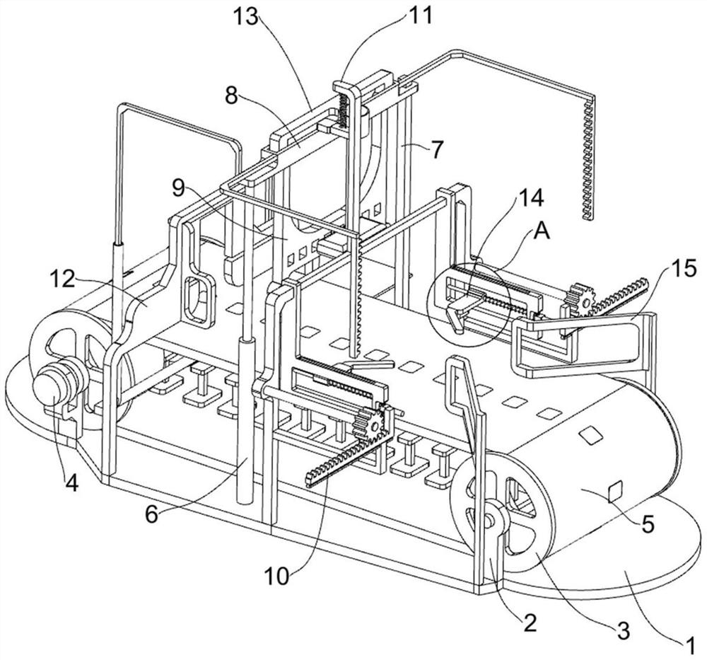
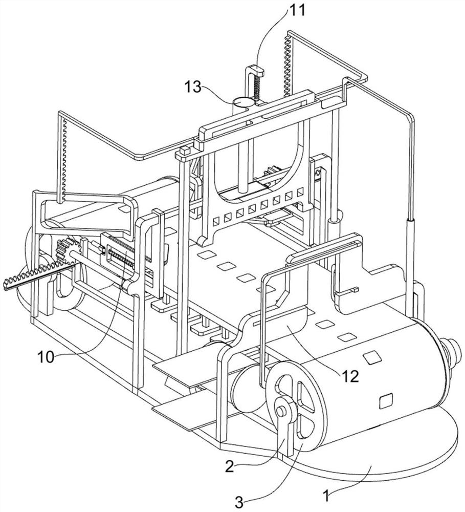
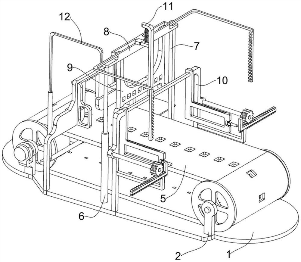
[0057] Such as figure 1 , figure 2 , image 3 , Figure 4 , Figure 5 , Image 6 , Figure 7 , Figure 8 , Figure 9 , Figure 10 , Figure 11 , Figure 12 , Figure 13 with Figure 14 As shown, this embodiment proposes an object transmission conveyor for the manufacture of new energy vehicles, including a bottom plate 1, legs 2, rollers 3, belt motor 4, perforated belt 5, electric push rod 6, a first guide Rod 7, sliding frame 8, clamping plate 9, finishing mechanism 10, control mechanism 11 and screening mechanism 12, the mode of rectangular distribution on the bottom plate 1 is fixedly connected with four supporting legs 2 by bolts, and the supporting legs 2 are rotatably connected with Roller 3, the two rollers 3 on the left side are symmetrical, the two rollers 3 on the right side are symmetrical, a belt motor 4 is fixed on the leg 2 on the left front, and the output shaft of the belt motor 4 is connected to the The roller 3 on the left front part is fixedly...
Embodiment 2
[0062] The scheme in embodiment 1 is further introduced below in combination with specific working methods, see the following description for details:
[0063] Such as Figure 15 with Figure 16 As shown, as a preferred embodiment, on the basis of the above method, it further includes a stabilizing mechanism 13, the stabilizing mechanism 13 is arranged on the top of the clamping plate 9, the stabilizing mechanism 13 is used to prevent the deformation of the object, and the stabilizing mechanism 13 includes The second fixed frame 131, the first slide bar 132 and the weight 133, the top of the clamping plate 9 is connected with the second fixed frame 131 by welding, the second fixed frame 131 is limited with the sliding frame 8, and the second fixed frame 131 A first slide bar 132 is slidably connected below, and a weight 133 is fixedly connected to the bottom of the first slide bar 132, and the weight 133 is used to press the top of the object.
[0064] Such as Figure 17 , ...
Embodiment 3
[0067] The schemes in Embodiment 1 and Embodiment 2 are further introduced below in conjunction with specific working methods, see the following description for details:
[0068] Specifically, when the new energy vehicle manufacturing object transmission conveyor is in use: first, the object is placed on the top of the perforated belt 5 through other equipment, and then the staff manually controls the belt motor 4 to start, and the belt motor 4 will pass through the output shaft. Drive the roller 3 located at the left front to rotate. Since the perforated belt 5 is wound on the four rollers 3, the roller 3 located at the left front will drive the remaining rollers 3 to rotate through the perforated belt 5. The perforated belt in rotation 5 will transport the objects on it toward the direction close to the screening frame 122, and at the same time, the staff will manually control the electric push rod 6 to shrink, and the electric push rod 6 will drive the sliding frame 8 and it...
PUM
 Abstract
Description
Claims
Application Information
 - R&D
- Intellectual Property
- Life Sciences
- Materials
- Tech Scout
- Unparalleled Data Quality
- Higher Quality Content
- 60% Fewer Hallucinations
Browse by: Latest US Patents, China's latest patents, Technical Efficacy Thesaurus, Application Domain, Technology Topic, Popular Technical Reports.
© 2025 PatSnap. All rights reserved.Legal|Privacy policy|Modern Slavery Act Transparency Statement|Sitemap|About US| Contact US: help@patsnap.com


