
More stable scientific research vibration experiment platform

An experimental platform and scientific research technology, applied in vibration testing, testing of machine/structural components, measuring devices, etc., can solve problems such as inability to realize circular shimmy motion, complex device structure, etc., and achieve good economy, applicability, and complexity The effect of less equipment and easy operation

Pending Publication Date: 2021-12-10
UNIV OF SCI & TECH LIAONING
View PDF3 Cites 2 Cited by
  • Summary
  • Abstract
  • Description
  • Claims
  • Application Information

AI Technical Summary

Problems solved by technology

[0005] Authorized public announcement number: CN 211099976 U discloses an invention patent "centrifugal force vibration platform", which is equipped with a transverse elastic expansion device, and the rotation of the centrifugal mechanism is driven by a driving motor, so that the entire vibration platform can realize multi-angle vibration up and down, left and right, However, circular shimmy motion cannot be achieved
[0006] Authorized public announcement number: CN 205914366 U discloses an invention patent "a vibration platform". The bottom of the vibration table is equipped with a slider, which is slidably connected with the guide rail, and the guide rail is installed on the base. The top can vibrate up and down and It can slide left and right, so that the device has the function of three-dimensional linear vibration, but the structure of the device is relatively complicated

Method used


Image

  • More stable scientific research vibration experiment platform
  • More stable scientific research vibration experiment platform
  • More stable scientific research vibration experiment platform

Examples


Embodiment Construction

[0026] The following will clearly and completely describe the technical solutions in the embodiments of the present invention with reference to the accompanying drawings in the embodiments of the present invention. Obviously, the described embodiments are only some, not all, embodiments of the present invention. Based on the embodiments of the present invention, all other embodiments obtained by persons of ordinary skill in the art without making creative efforts belong to the protection scope of the present invention.

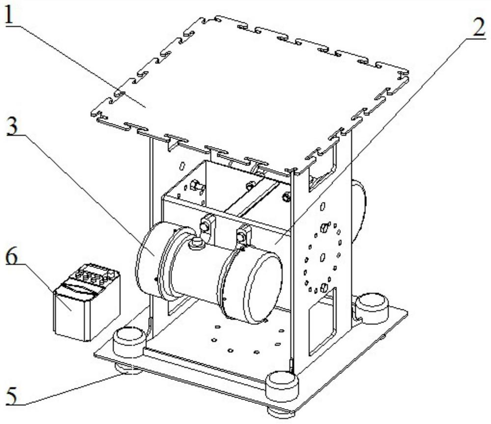
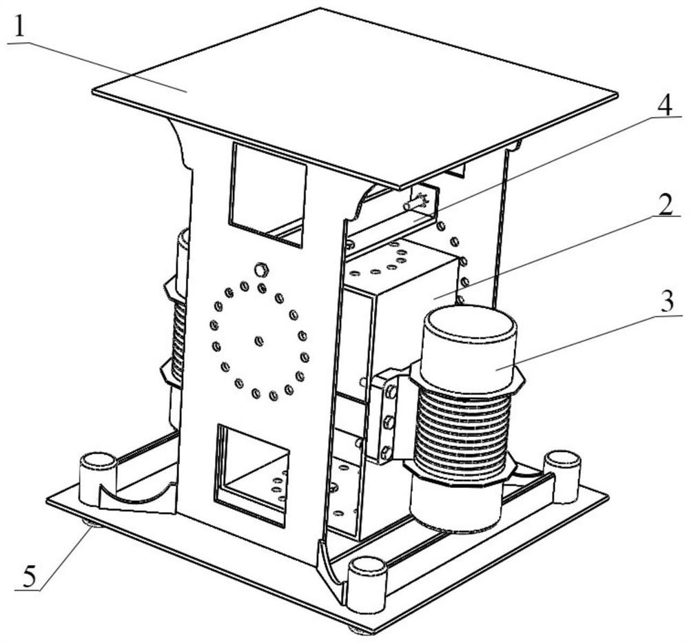
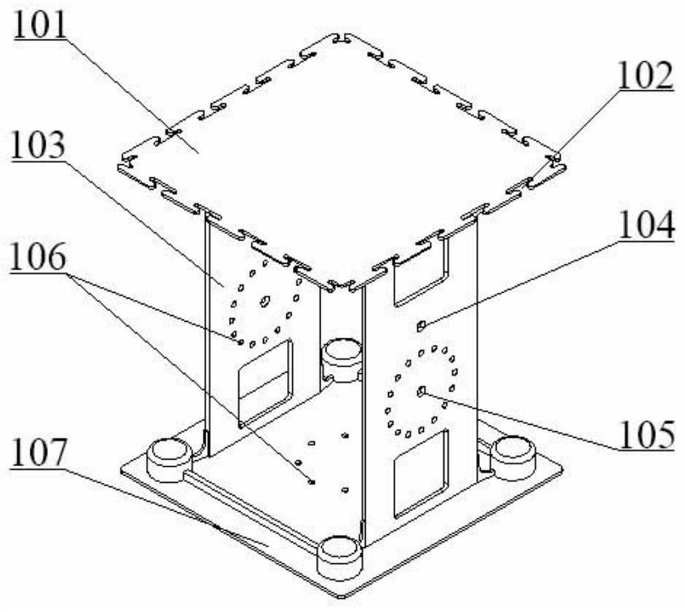
[0027] See figure 1 , Figure 3-6 , is a structural schematic diagram of a more stable scientific research vibration experiment platform embodiment 1 of the present invention, including a vibration box 1, a vibration motor 3, a positioning frame 2 and a controller 6, and the vibration box 1 is provided with a positioning frame 2 and a positioning frame Two vibrating motors 3 are arranged symmetrically on 2; the vibrating box 1 is a square frame, including a w...


PUM

PropertyMeasurementUnit
Diameteraaaaaaaaaa

Abstract

The invention relates to the technical field of vibration devices, in particular to a more stable scientific research vibration experiment platform which is characterized in that the platform comprises a vibration box body, vibration motors, a positioning frame and a controller, the positioning frame is arranged in the vibration box body; the two vibration motors are symmetrically arranged on the positioning frame; the vibration box body is a square frame and comprises a working platform on the top, side plates on the two sides and a bottom plate, elastic ground feet are arranged at the four corners of the bottom plate, mounting clamping grooves used for fixing working parts are formed in the working platform, and positioning holes are correspondingly formed in the two sides of the positioning frame, the side plates and the bottom plate; and the angle of the exciting force of the motor can be changed by adjusting the inclination angle of the positioning frame relative to the bottom plate, so that different forms of vibration are generated. The platform has the advantages that by changing the fixing mode of the positioning frame, the experiment requirements of circumferential shimmy or linear vibration and combined vibration in the horizontal direction are met, experiment equipment does not need to be replaced, the structure is simple, one machine has multiple purposes, and better economical efficiency and applicability are achieved.

Description

technical field [0001] The invention relates to the technical field of vibration devices, in particular to a more stable scientific research vibration experiment platform, which can realize multi-angle linear vibration and horizontal circular shimmy vibration, and meet the needs of any or combined vibration experiments. Background technique [0002] The research on the dynamics of particulate matter under different vibration forms has always been a hot topic in the eyes of scholars. The existing vibration experiment platforms on the market can only achieve a single vibration. Different vibration experiments require different vibration equipment, and in combination vibration During the experiment, the experimental platform needs to be replaced. Since the object of the experiment is often discrete element particles, it is difficult to ensure the particle configuration when changing the platform. Due to the great difference in the working parts of different types of experiments...

Claims


Application Information

Patent Timeline
IPC IPC(8): G01M7/02
CPCG01M7/022G01M7/025
Inventor 李玲玲陈晨黄涛周大鹏张凡杜昱霖刘金山程中强马学东
Owner UNIV OF SCI & TECH LIAONING
Learn More