
Straw recycling equipment and recycling method thereof

A straw and equipment technology, applied in straw recycling equipment and its recycling field, can solve the problems of uneven accumulation, low recycling efficiency, blockage, etc., and achieve the effect of increasing the storage space and reducing the probability of straw discharge.

Inactive Publication Date: 2021-12-14
凤台县淮之苗农业发展有限公司
View PDF5 Cites 0 Cited by
  • Summary
  • Abstract
  • Description
  • Claims
  • Application Information

AI Technical Summary

Problems solved by technology

[0003] After the traditional straw recycling device shreds the straw, the straw in the fragmented state cannot be effectively discharged, and it is easy to accumulate inside the straw recycling device, which is easy to cause blockage and low recovery efficiency. At the same time, because the straw in the fragmented state is relatively light, Discharging towards the same angle is likely to cause uneven accumulation, requiring manual leveling of the accumulated straw

Method used


Image

  • Straw recycling equipment and recycling method thereof
  • Straw recycling equipment and recycling method thereof
  • Straw recycling equipment and recycling method thereof

Examples


Embodiment 1

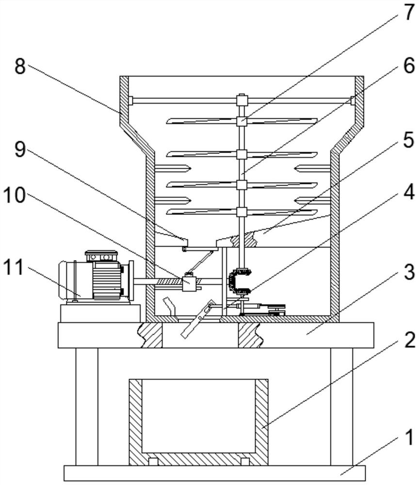
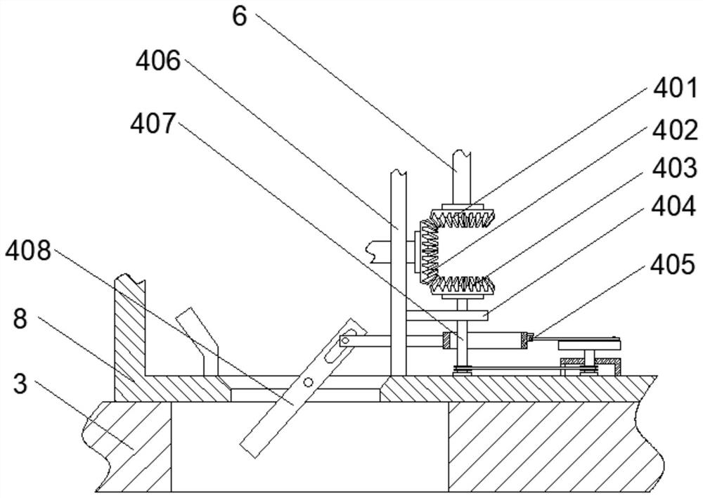
[0034] see figure 2As shown, the above-mentioned adjustment mechanism 4 includes a third partition 406 fixedly connected to the first partition 5, the third partition 406 is arranged vertically, and a first bevel gear 402 is provided on one side of the third partition 406, and the first bevel gear 402 is arranged on the first partition 406. The bevel gear 402 is connected to the first rotating shaft 6 through the second bevel gear 401, the first bevel gear 402 is connected to the second rotating shaft 407 through the third bevel gear 403, and the bottom end of the second rotating shaft 407 is connected to the shell 8 through the bearing. The inner wall is rotatably connected, through the rotation of the first bevel gear 402 and the rotation of the second bevel gear 401 and the third bevel gear 403 to drive the first rotating shaft 6 and the second rotating shaft 407 to rotate respectively, so as to provide power output for the cutter 7 to cut straw, and the third partition 40...

Embodiment 2

[0038] see Figure 5 and Figure 6 As shown, the above-mentioned opening mechanism 10 includes a threaded screw rod 1005, the middle part of the threaded screw rod 1005 is threadedly connected with an installation sleeve 1003, and the top of the installation sleeve 1003 is movably connected with a push-pull rod 1002 through a rotating seat, and one end of the push-pull rod 1002 is hinged with an opening. Closing the door 1001, one end of the opening and closing door 1001 is hinged with the second partition 9, a guide rod 1004 is arranged below the threaded screw rod 1005, the guide rod 1004 moves through the bottom of the installation sleeve 1003, and the installation sleeve 1003 moves through the guide rod 1004 Limit support is provided, and at the same time, the push-pull rod 1002 is driven to open or close the opening and closing door 1001 through the movement of the installation sleeve 1003, so as to facilitate the control of the amount of straw discharged in a fragmented ...


PUM


Abstract

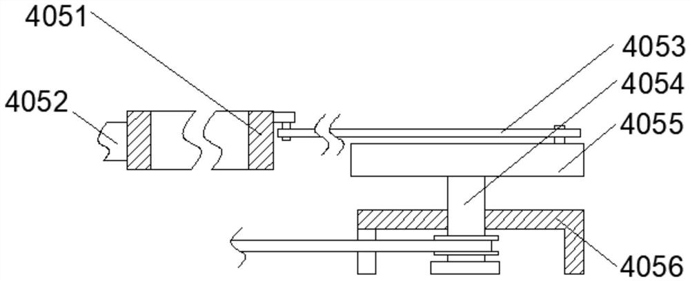
The invention relates to straw recycling equipment and a recycling method thereof. The straw recycling equipment comprises a supporting plate, a shell is fixedly installed at the top of the supporting plate, a cavity is formed in the shell, a first partition plate and a second partition plate are fixedly installed in the middle of the shell, an adjusting mechanism used for changing the straw discharging position is arranged below the first partition plate, an opening mechanism used for controlling the straw discharging speed is arranged below the second partition plate, rotating of a rotary disc is matched with a transmission rod to drive a limiting block and two moving rods to move, the angle of an adjusting plate can be conveniently adjusted, the discharging angle and position of straw in a fragment state are changed, the process of manually leveling the straw is reduced, the storage space of a storage box is increased, a push-pull rod is driven by a mounting sleeve to open an opening and closing door, the straw in a fragmented state falls down, discharging of the straw in the fragmented state is conveniently controlled, and then the situation that the straw is accumulated in the shell and is stuck is reduced.

Description

technical field [0001] The invention relates to the technical field of straw recycling, in particular to straw recycling equipment and a recycling method thereof. Background technique [0002] Straw, called stalks in ancient times, also known as grass straw, refers to the remaining stems and leaves of gramineous crops such as rice, wheat, and corn after threshing. Among them, rice straw is often called rice straw and rice straw, and wheat straw is called Wheat straw; before industrialization, farmers used straw in various ways, which was very abundant and was rarely wasted directly; however, due to the popularization of coal, electricity, natural gas, and the abundance of various industrial products in China in the past two decades, the use of straw in rural areas Demand has decreased, and the disposal of large amounts of straw has become a serious social problem. [0003] After the traditional straw recycling device shreds the straw, the straw in the fragmented state canno...

Claims


Application Information

Patent Timeline
Patent Type & Authority Applications(China)
IPC IPC(8): A01F29/02A01F29/09A01F29/12
CPCA01F29/025A01F29/095A01F29/09A01F29/12
Inventor 陈运陈传安童晓红关立松王立涛王树飞高矿
Owner 凤台县淮之苗农业发展有限公司
Learn More