Electrode bar horizontal cutting device for electrolytic aluminum

A technology of electrode rods and electrolytic aluminum, which is applied in the field of aluminum electrolysis, can solve the problems of inability to accurately ensure the same length of electrode rods and low processing efficiency, and achieve the effects of improved cutting efficiency, convenient operation, and compact structure

Pending Publication Date: 2021-12-14
HENAN WANJI ALUMINUM
View PDF5 Cites 0 Cited by
  • Summary
  • Abstract
  • Description
  • Claims
  • Application Information

AI Technical Summary

Problems solved by technology

[0002] Electrolytic aluminum uses electrode rods to precipitate aluminum. In order to ensure the quality of electrolytic aluminum, it is necessary to cut each batch of electrode rods into the same length. The current cutting method is to cut and process individually by manual scribing. Precisely ensure the same length of the electrode rod after cutting

Method used


Image

  • Electrode bar horizontal cutting device for electrolytic aluminum
  • Electrode bar horizontal cutting device for electrolytic aluminum
  • Electrode bar horizontal cutting device for electrolytic aluminum

Examples


Embodiment 1

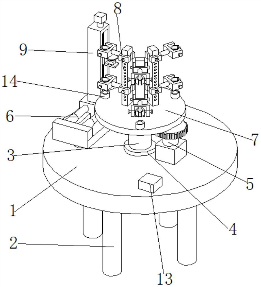
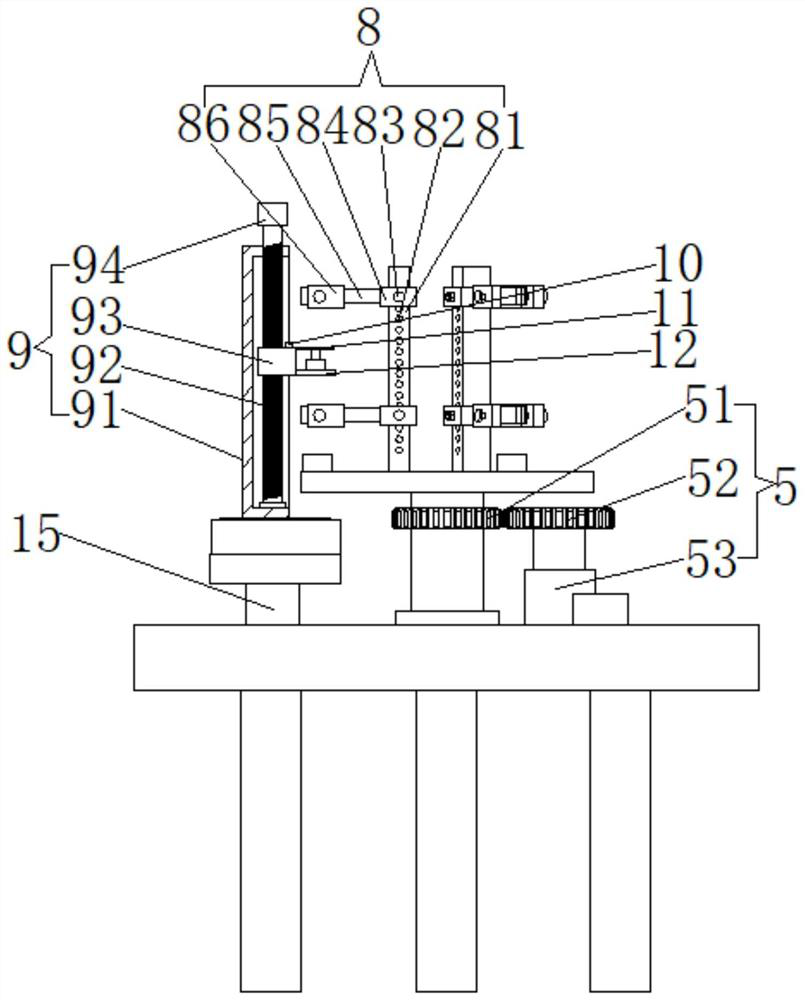
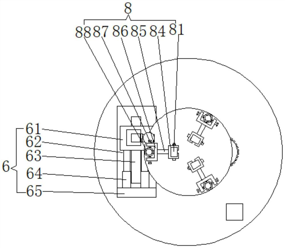
[0019] Example 1: See Figure 1-3 , the present invention provides a technical solution: an electrode rod flat cutting device for electrolytic aluminum, comprising a bottom plate 1, the lower end surface of the bottom plate 1 is provided with a leg 2, and the upper end surface of the bottom plate 1 is rotatably connected with a rotating shaft 3 through a bearing 4, One side of the rotating shaft 3 is provided with a driving mechanism 5 for driving its rotation. The driving mechanism 5 includes a driven gear 51, a driving gear 52 and a driving motor 53. The driven gear 51 is sleeved on the outer surface of the rotating shaft 3. The driving gear 52 and the The driven gear 51 is meshed and connected, and the driving gear 52 is connected with the output shaft of the driving motor 53. The cooperation of the driving gear 52 and the driven gear 51 drives the rotating shaft 3 to rotate, which can ensure the stability of the rotating shaft 3. The upper end of the rotating shaft 3 is pro...

Embodiment 2

[0021]Embodiment 2: The difference from Embodiment 2 is that the outer surface of the vertical rod 81 is evenly distributed with a plurality of perforations 82 along its height direction, and the sliding sleeve 84 is provided with through holes corresponding to the positions of the perforation 82. 84 and the vertical rod 81 are fixed together by the fixed screw rod 83, and the position of the sliding sleeve 84 can be adjusted according to the difference in the cutting length required for each batch of electrode rods by providing a plurality of through holes on the vertical rod 81 to ensure that the clamping Block 84 for stability of electrode rod clamping.


PUM


Abstract

The invention discloses an electrode bar horizontal cutting device for electrolytic aluminum. The electrode bar horizontal cutting device comprises a bottom plate. Supporting legs are arranged on the lower end face of the bottom plate, a rotating shaft is rotationally connected to the upper end face of the bottom plate through a bearing, a driving mechanism which is used for driving the rotating shaft to rotate is arranged on one side of the rotating shaft, and a fixing disc is arranged at the upper end of the rotating shaft. At least two clamping mechanisms which are used for clamping electrode bars are evenly distributed at the upper end of the fixing disc, a cutting machine is arranged on one side of the fixing disc and fixed to the upper end of a supporting plate, and the supporting plate is connected with a lifting mechanism which is used for controlling the cutting machine to move up and down. A displacement sensor is arranged on the lifting mechanism, the displacement sensor and the cutting machine move at the same time, and the displacement sensor and a cutting wheel on the cutting machine are located on the same plane. According to the electrode bar horizontal cutting device for electrolytic aluminum, the cutting efficiency can be effectively improved, it is guaranteed that the lengths of the electrode bars in each batch are the same, and the use convenience is greatly improved.

Description

technical field [0001] The invention relates to the technical field of aluminum electrolysis, in particular to an electrode rod flat cutting device for electrolytic aluminum. Background technique [0002] Electrolytic aluminum uses electrode rods to precipitate aluminum. In order to ensure the quality of electrolytic aluminum, it is necessary to cut each batch of electrode rods into the same length. The current cutting method is to cut and process individually by manual scribing. Precisely ensure that the length of the electrode rod after cutting is the same. Contents of the invention [0003] The technical problem to be solved by the present invention is to overcome the existing defects and provide a flat cutting device for electrode rods for electrolytic aluminum, which can effectively improve the cutting efficiency and ensure that the length of each batch of electrode rods is the same, which can effectively solve the problems in the background technology. The problem. ...

Claims


Application Information

Patent Timeline
Patent Type & Authority Applications(China)
IPC IPC(8): B28D1/24B28D7/04B28D7/00C25C3/08C25C3/12
CPCB28D1/24B28D7/04B28D7/005B28D7/00C25C3/08C25C3/12
Inventor 邵伟峰邵长军李向军张建立王小宝
Owner HENAN WANJI ALUMINUM
Why Eureka
Try Eureka