Preparation method of infilled wall component
A technology for filling walls and components, which is applied to building components, walls, building structures, etc. It can solve the problems of heavy weight, loud noise, and more construction waste of a single board, and achieves improved mechanization, less consumables, and good integrity Effect
- Summary
- Abstract
- Description
- Claims
- Application Information
AI Technical Summary
Problems solved by technology
Method used
Image

Examples
Embodiment 1
[0044] This embodiment is a preparation method of filling wall components, and the specific process is as follows:
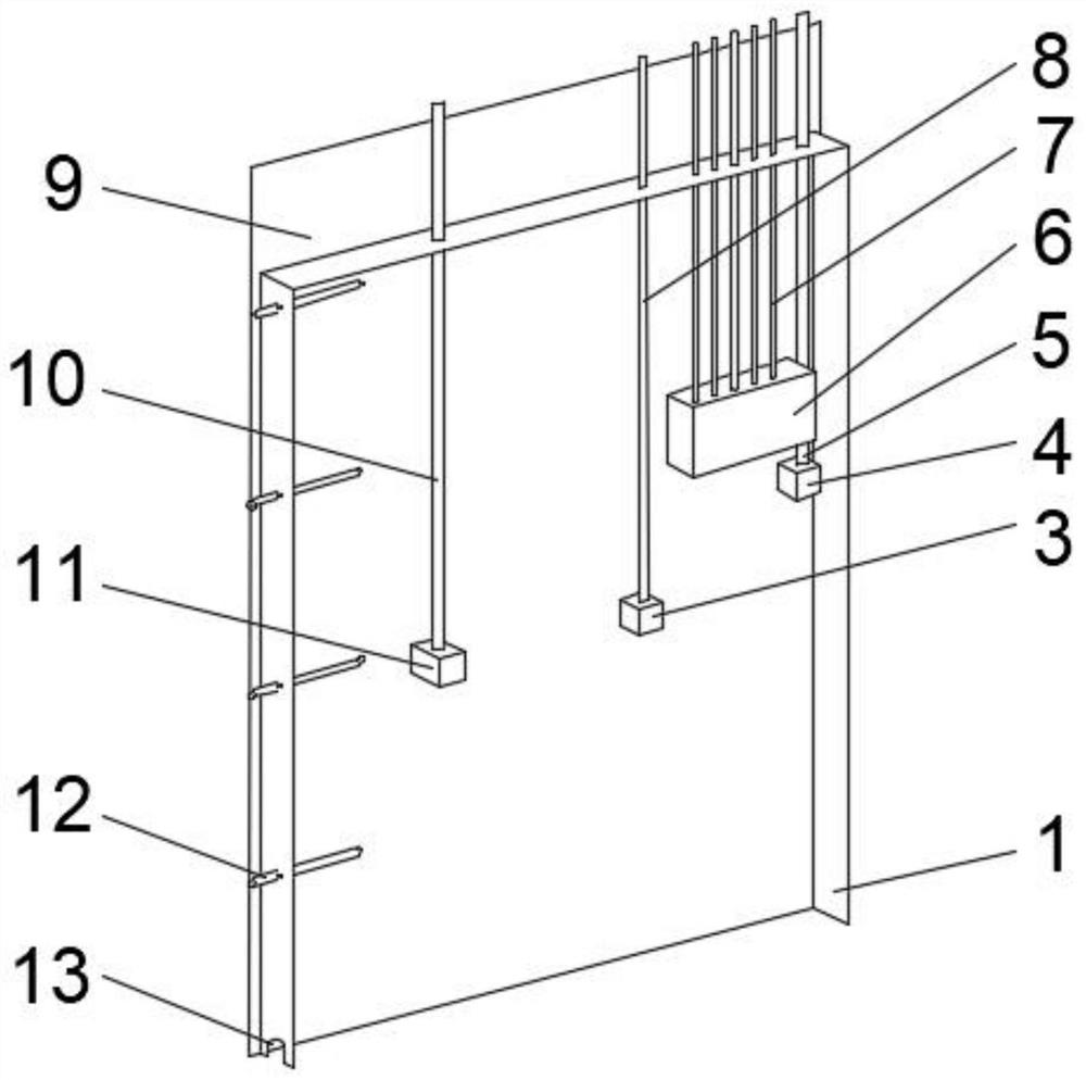
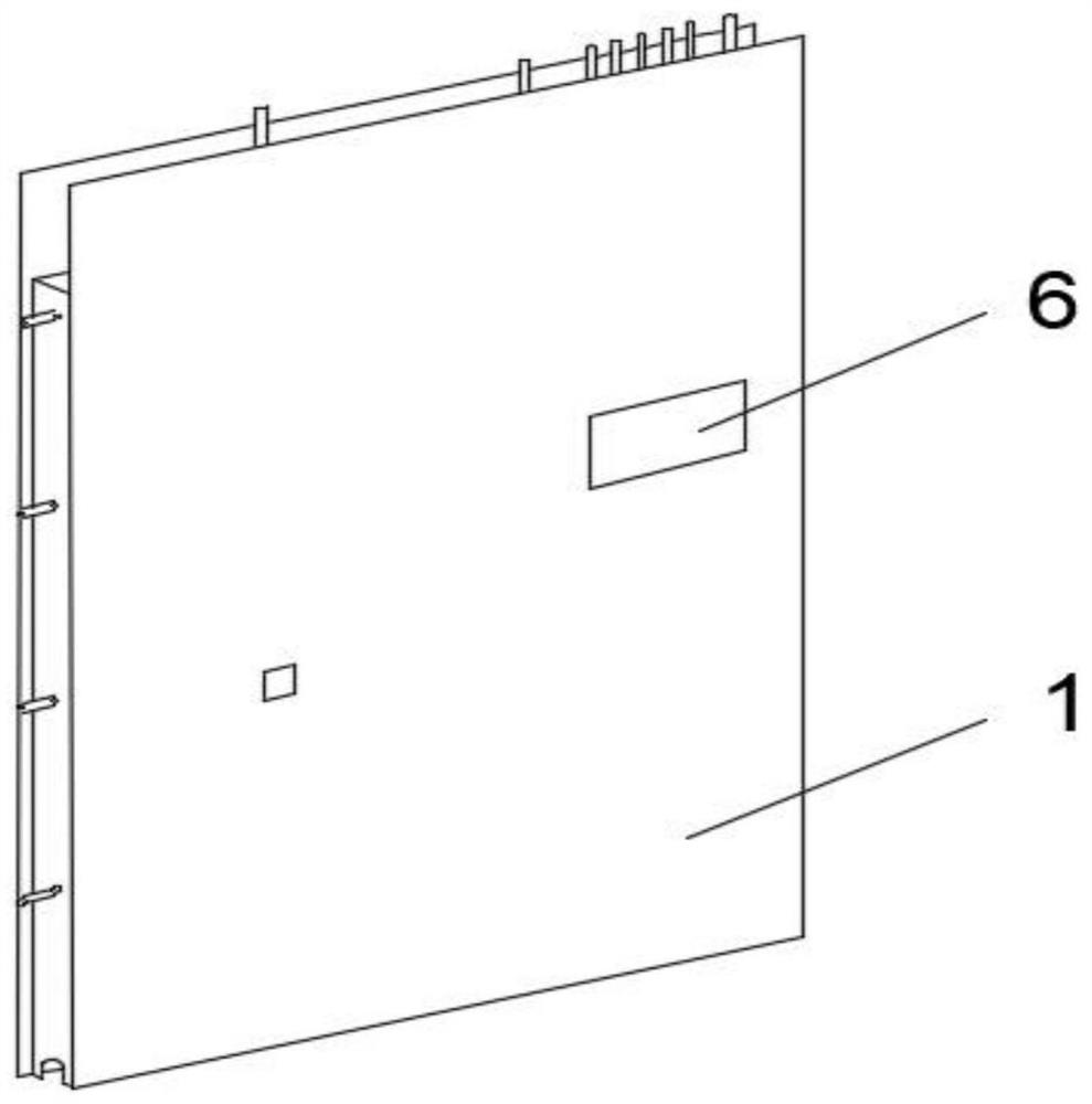
[0045] S1: Set up the prefabricated mold according to the specifications and dimensions required by the building construction drawings, and prepare the pre-embedded wire box, wire pipe and pre-embedded wire box 6 for use;
[0046] S2: inject mortar into the prefabricated mold, place the connecting steel bar 12 on one side, pour it to 2 cm, and let it stand for initial setting to obtain the beam formwork 9 and the first wall 14;
[0047] S3: Add 1 cm of lightweight filler to the first wall 14, and connect the first pre-embedded wire pipe 10 and the first pre-embedded wire box 11 according to the specifications, and the second pre-embedded wire pipe 8 and the second pre-embedded The wire box 3 is fixedly connected, the third pre-embedded wire pipe 7 is fixedly connected to the pre-embedded wire box 6, the fourth pre-embedded wire box 4 is connected to the fourth p...
Embodiment 2
[0058] This embodiment is a preparation method of filling wall components, and the specific process is as follows:
[0059] S1: Set up the prefabricated mold according to the specifications and dimensions required by the building construction drawings, and prepare the pre-embedded wire box, wire pipe and pre-embedded wire box 6 for use;
[0060] S2: inject mortar into the prefabricated mold, place the connecting steel bar 12 on one side, pour it to 2 cm, and let it stand for initial setting to obtain the beam formwork 9 and the first wall 14;
[0061] S3: Add 1 cm of lightweight filler to the first wall 14, and connect the first pre-embedded wire pipe 10 and the first pre-embedded wire box 11 according to the specifications, and the second pre-embedded wire pipe 8 and the second pre-embedded The wire box 3 is fixedly connected, the third pre-embedded wire pipe 7 is fixedly connected to the pre-embedded wire box 6, the fourth pre-embedded wire box 4 is connected to the fourth p...
Embodiment 3
[0072] This embodiment is a preparation method of filling wall components, and the specific process is as follows:
[0073] S1: Set up the prefabricated mold according to the specifications and dimensions required by the building construction drawings, and prepare the pre-embedded wire box, wire pipe and pre-embedded wire box 6 for use;
[0074] S2: inject mortar into the prefabricated mold, place the connecting steel bar 12 on one side, pour it to 3 cm, and let it stand for initial setting to obtain the beam formwork 9 and the first wall 14;
[0075] S3: Add 2 cm of lightweight filler to the first wall 14, and connect the first pre-embedded wire pipe 10 and the first pre-embedded wire box 11 according to the specifications, and the second pre-embedded wire pipe 8 and the second pre-embedded The wire box 3 is fixedly connected, the third pre-embedded wire pipe 7 is fixedly connected to the pre-embedded wire box 6, the fourth pre-embedded wire box 4 is connected to the fourth p...
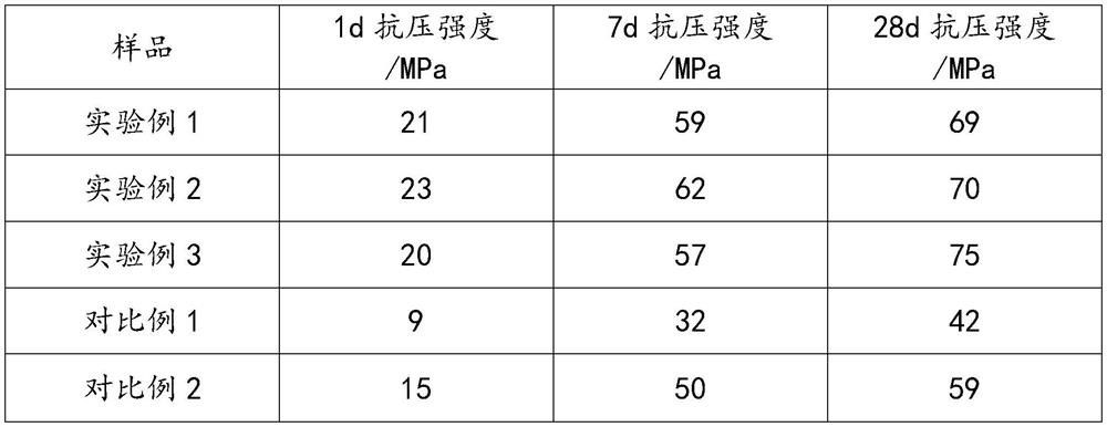
PUM
| Property | Measurement | Unit |
|---|---|---|
| Compressive strength | aaaaa | aaaaa |
| Compressive strength | aaaaa | aaaaa |
| Compressive strength | aaaaa | aaaaa |
Abstract
Description
Claims
Application Information
 - R&D
- Intellectual Property
- Life Sciences
- Materials
- Tech Scout
- Unparalleled Data Quality
- Higher Quality Content
- 60% Fewer Hallucinations
Browse by: Latest US Patents, China's latest patents, Technical Efficacy Thesaurus, Application Domain, Technology Topic, Popular Technical Reports.
© 2025 PatSnap. All rights reserved.Legal|Privacy policy|Modern Slavery Act Transparency Statement|Sitemap|About US| Contact US: help@patsnap.com