Daily collision recovery type anti-collision column and construction method thereof
An anti-collision column, a daily technology, applied in the direction of infrastructure engineering, roads, buildings, etc., can solve the problems of poor waterproof performance at the joint, complex connection structure of non-fixed anti-collision column, affecting underground pipelines, etc., to enhance local connection. performance, improve the effect of anti-collision, and save the cost of materials
- Summary
- Abstract
- Description
- Claims
- Application Information
AI Technical Summary
Problems solved by technology
Method used
Image
Examples
Embodiment 1
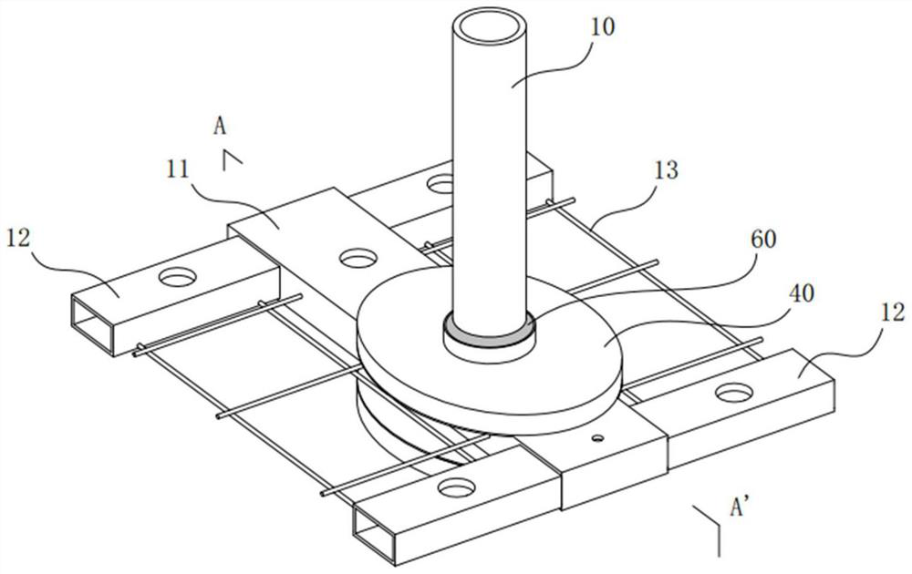
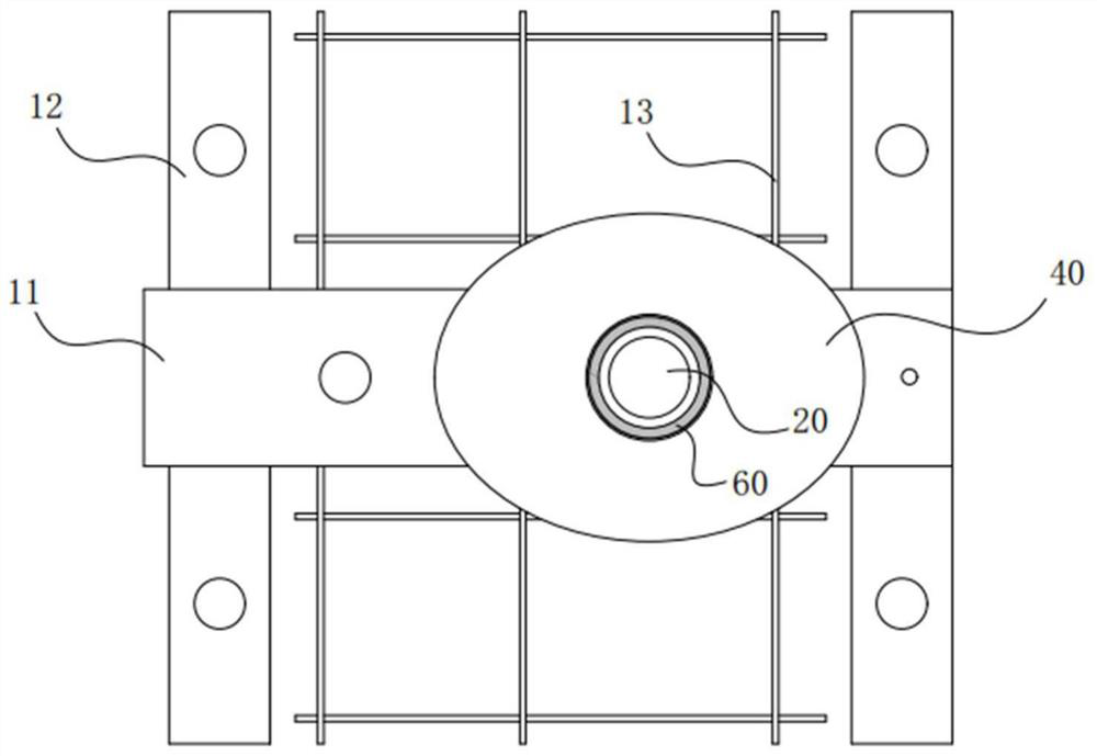
[0051] Such as Picture 1-1As shown in 0, a daily collision recovery type anti-collision column, the anti-collision column includes a column 20 inserted in the foundation 10, and the foundation 10 is composed of a steel mesh 13, concrete, a horizontal steel box 11 immersed in the concrete and no It is placed in the concrete and arranged at both ends of the horizontal steel box 11, and is composed of a vertical steel box 12 for connecting and fixing the horizontal steel box 11.
[0052] The upright column 20 is inserted into the transverse steel box 11, and the connection position between the upright column 20 and the foundation 10 is provided with a collision recovery device.
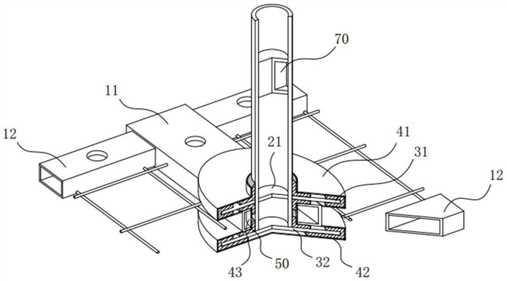
[0053] The crash recovery device includes a steel plate 30 with a through hole and a steel cavity 40 wrapping the steel plate 30, the steel cavity 40 is provided with a through hole corresponding to the column 20, and the bottom end of the column 20 is inserted In the through hole, the column 20 is fix...
Embodiment 2
[0068] For example, in the daily collision recovery anti-collision column in Example 1, when the second steel plate 32 is an integral steel plate, the construction method steps are as follows:
[0069] S1. After the horizontal steel box 11 and the vertical steel box 12 are set, a hole for inserting the upright 20 is opened on the horizontal steel box 11, and the connecting steel plate 43 is welded in the hole first, and then the upright 20 is inserted into the hole;
[0070] S2. Weld the second steel plate 32 at the bottom of the column 20, set the first rubber cushion layer 51 on the edge of the second steel plate 32, and then set the second rubber cushion layer 52 at the connection between the second steel plate 32 and the column 20, and weld the second steel container The top cover 40b of the cavity 42 ensures that the top cover 40b is attached to the lower surface of the horizontal steel box 11, and then the bottom plate 40a is welded under the top cover 40b;
[0071] S3. ...
Embodiment 3
[0080] The present invention does not specifically limit the specific size of the anti-collision post, which can be set according to actual needs. However, in practical applications, in order to achieve the best impact recovery, the maximum deflection angle θ of the column of the anti-collision column should not exceed 2°.
[0081] The formula for calculating the deflection angle θ is as follows:
[0082]
[0083] Among them, σ is the maximum lateral deflection of the top of column 20, and the calculation formula is as follows:
[0084]
[0085] In the formula: c is the maximum compressibility of the elastic material 50, t 1 For elastic material 50 use thickness, t 2 is the thickness of the steel plate 30, r is the radius of the major axis of the steel cavity 40, d is the foundation depth of the column 20 (that is, the vertical distance from the bottom surface of the column 20 to the ground), and H is the total height of the column 20.
[0086] Taking the anti-collisi...
PUM
 Abstract
Description
Claims
Application Information
 - R&D
- Intellectual Property
- Life Sciences
- Materials
- Tech Scout
- Unparalleled Data Quality
- Higher Quality Content
- 60% Fewer Hallucinations
Browse by: Latest US Patents, China's latest patents, Technical Efficacy Thesaurus, Application Domain, Technology Topic, Popular Technical Reports.
© 2025 PatSnap. All rights reserved.Legal|Privacy policy|Modern Slavery Act Transparency Statement|Sitemap|About US| Contact US: help@patsnap.com


