IGBT module cooling method

A technology of an oven and a cooling cavity, which is applied in the field of semiconductor product production technology, can solve the problems of long cooling time, low production efficiency, and few monitoring means, and achieves the effects of high cooling efficiency and improved production efficiency.

Pending Publication Date: 2021-12-14
安徽瑞迪微电子有限公司
View PDF0 Cites 0 Cited by
  • Summary
  • Abstract
  • Description
  • Claims
  • Application Information

AI Technical Summary

Problems solved by technology

Occupies the factory workshop space, and the equipment is relatively heavy, which is not conducive to the implementation of the factory's future planning
The IGBT module is cooled by natural cooling, which takes a long time to cool down, resulting in low production

Method used


Image

  • IGBT module cooling method

Examples


Embodiment Construction

[0014] The specific embodiment of the present invention will be described in further detail by describing the embodiments below with reference to the accompanying drawings, the purpose is to help those skilled in the art to have a more complete, accurate and in-depth understanding of the concept and technical solutions of the present invention, and contribute to its implementation.

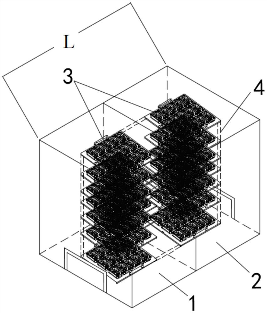
[0015] like figure 1 As shown, the present invention provides a kind of IGBT module cooling method, comprises the steps:

[0016] S1. An oven is provided, and the oven has a cooling chamber 1;

[0017] S2. Place the IGBT module in the cooling chamber 1 of the oven to cool down the IGBT module.

[0018] Specifically, as figure 1 As shown, a heating chamber 2 and a cooling chamber 1 are arranged inside the oven, and the heating chamber 2 and the cooling chamber 1 are independently controlled. In the above step S2, the IGBT modules are transported by the carrying rail 4 into the cooling cavity 1 ...


PUM


Abstract

The invention discloses an IGBT module cooling method. The method comprises the following steps: S1, providing an oven which is provided with a cooling cavity; and S2, placing an IGBT module the cooling cavity of the oven, and cooling the IGBT module. According to the IGBT module cooling method, the cooling cavity is additionally formed in the oven, cooling of the IGBT module is achieved, the cooling efficiency is high, and the production efficiency can be improved.

Description

technical field [0001] The invention belongs to the technical field of semiconductor product production technology, in particular, the invention relates to a cooling method for an IGBT module. Background technique [0002] For traditional IGBT module packaging, after the semi-finished module is installed in the shell, glue filling process is required inside, and the glue is cured in the oven at a high temperature of 100°C for half an hour. In view of the fact that the cured module needs to be cooled to 50°C before it can be released from the furnace, and there is no cooling function in the furnace, so natural cooling can only be used to achieve the cooling effect. [0003] The size of the existing curing furnace equipment is too large, and the general length reaches 5-6 meters. Occupies the workshop space of the factory, and the equipment is cumbersome, which is not conducive to the implementation of the factory's future planning. The IGBT module is cooled by natural cooli...

Claims


Application Information

Patent Timeline
IPC IPC(8): H01L21/67F27D9/00
CPCH01L21/67121H01L21/67098F27D9/00F27D2009/001
Inventor 杨幸运陶少勇陈小磊罗凯
Owner 安徽瑞迪微电子有限公司
Why Eureka
Try Eureka