
Symbol determination device and symbol determination method

A technology for determining devices and symbols, applied in digital transmission systems, equalizers, baseband systems, etc., to achieve the effect of suppressing the increase in the amount of computation

Pending Publication Date: 2021-12-14
NIPPON TELEGRAPH & TELEPHONE CORP
View PDF7 Cites 0 Cited by
  • Summary
  • Abstract
  • Description
  • Claims
  • Application Information

AI Technical Summary

Problems solved by technology

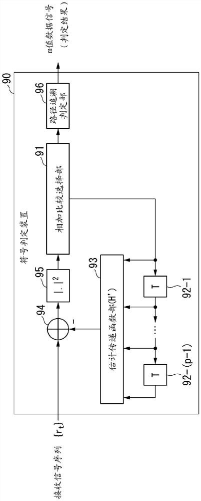
Again, since a negative sign is attached to the delay amount, delay 81 provides a negative delay of "LT"

Method used


Image

  • Symbol determination device and symbol determination method
  • Symbol determination device and symbol determination method
  • Symbol determination device and symbol determination method

Examples


no. 1 approach )

[0084] Hereinafter, embodiments of the present invention will be described with reference to the drawings.

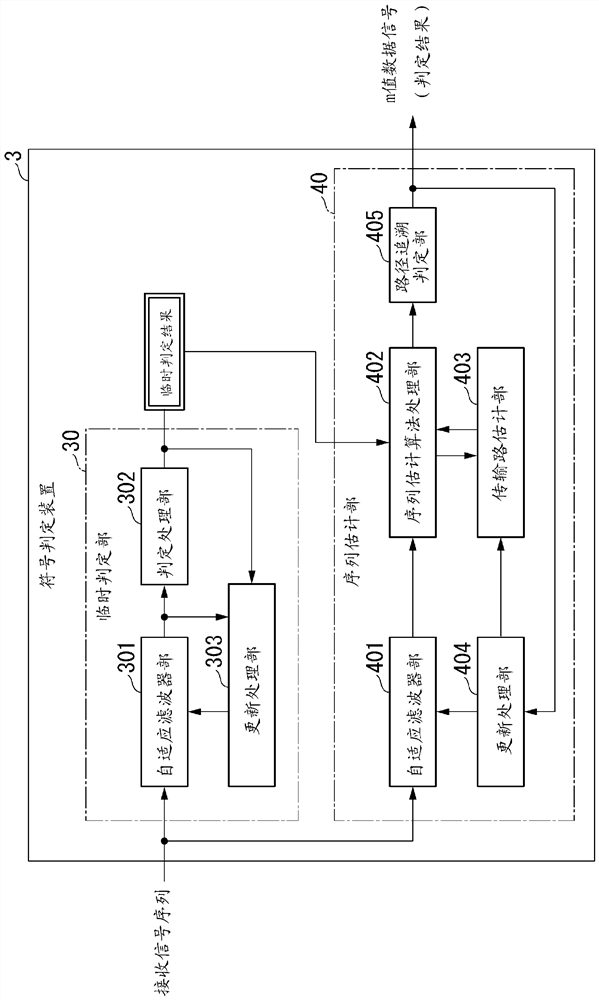
[0085] figure 1 It is a block diagram showing the configuration of the communication system S in the first embodiment. The communication system S includes a signal generation device 1 , a transmission path 2 and a sign determination device 3 .

[0086] Signal generating device 1 and transmission path 2 with Figure 18 The signal generating device 1 and the transmission line 2 included in the conventional communication system 100 shown in FIG. 2 have the same configuration. The signal generator 1 takes in an m-value data signal supplied from outside. m is a sign multivalued degree, for example, an integer of 2 or more. Each symbol is represented by a numeral or a sign. For example, in the case of m=8, each symbol is represented by a number [0, 1, 2, 3, 4, 5, 6, 7].

[0087] The signal generation device 1 uses the imported m-value data signal as a transmission symb...

no. 2 approach )

[0182] Figure 10 is a block diagram showing the internal configuration of the symbol determination device 3a in the second embodiment, Figure 11 It is a block diagram showing a detailed internal configuration of the symbol determination device 3 a in the second embodiment. In the second embodiment, the same reference numerals are assigned to the same configurations as those in the first embodiment, and different configurations will be described below.

[0183] Such as Figure 10 As shown, the symbol determination device 3a includes a provisional determination unit 30 and a sequence estimation unit 40a. The sequence estimation unit 40 a includes an adaptive filter unit 401 a , a sequence estimation algorithm processing unit 402 , a channel estimation unit 403 , an update processing unit 404 , and a path tracing determination unit 405 .

[0184] An input terminal of the adaptive filter unit 401 a is connected to an output terminal of the adaptive filter unit 301 of the prov...


PUM


Abstract

A method comprises: generating a symbol sequence by subjecting a reception signal sequence taken in from a transmission path to adaptive equalization by an estimated inverse-transfer function of the transmission path; performing provisional determination with respect to the generated symbol sequence; generating a plurality of symbol sequences indicating a transmission path state in a range between a provisionally determined symbol obtained by the provisional determination and a symbol in a vicinity of the provisionally determined symbol; on the basis of the plurality of generated symbol sequences indicating the transmission path state and an estimated transfer function of the transmission path, generating an estimated reception symbol sequence for each transmission path state; calculating a metric between a symbol sequence obtained from the reception signal sequence and each of the estimated reception symbol sequences; and determining a transmission symbol sequence by selecting a most likely estimated reception symbol sequence on the basis of the calculated metric, the provisionally determined symbol, and the symbol in the vicinity of the provisionally determined symbol.

Description

technical field [0001] The present invention relates to a symbol judging device and a symbol judging method. Background technique [0002] Due to the rapid spread of smart phones and tablet PCs in recent years and the increase of various rich content in high-definition video distribution services, etc., the traffic transferred by the backbone network of the Internet has continued to increase. In addition, the utilization of cloud services in enterprises is also advancing. From this, it is predicted that in a data center (hereinafter, referred to as “DC” (Data Center)), the traffic volume of the inter-DC network increases at an annual rate of about 1.3 times. [0003] Currently, Ethernet (registered trademark) is mainly introduced as a connection method within DC or between DCs. It is expected that it will be difficult to increase the size of DCs in a single site along with the increase in communication traffic. Therefore, in the future, the need for cooperation between DC...

Claims


Application Information

Patent Timeline
Patent Type & Authority Applications(China)
IPC IPC(8): H03M13/41
CPCH03M13/41H04L25/03248H04L2025/03471H04L27/01
Inventor 谷口宽树中村政则山本秀人增田阳木坂由明
Owner NIPPON TELEGRAPH & TELEPHONE CORP
Learn More