Encoding method, decoding method, encoding device and decoding device
A technology of encoding method and decoding method, applied in code conversion, television, electrical components, etc., can solve problems such as difficult to use KLT, large amount of transformation coefficient data, and large amount of calculation
- Summary
- Abstract
- Description
- Claims
- Application Information
AI Technical Summary
Problems solved by technology
Method used
Image
Examples
Embodiment approach 1
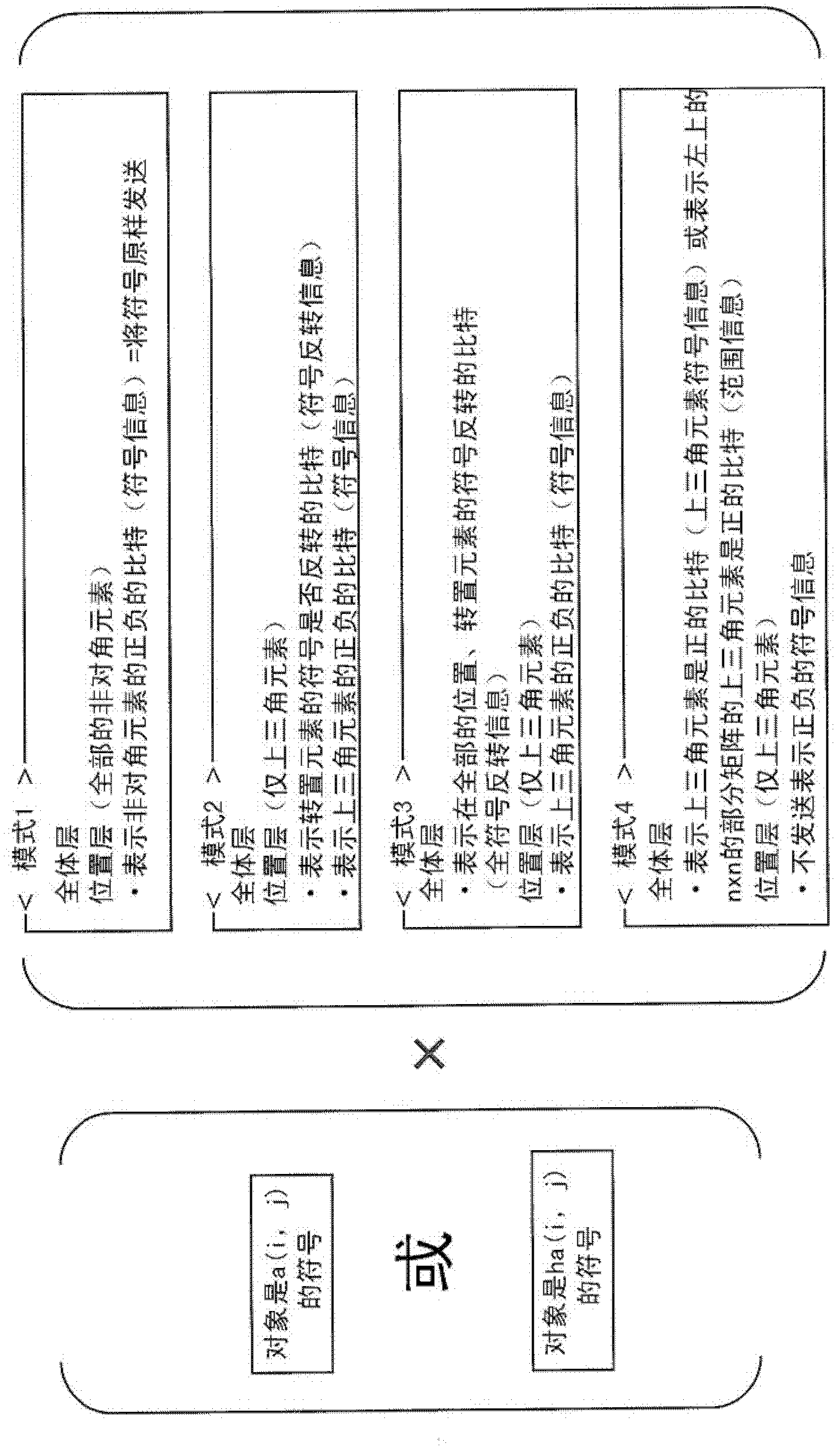
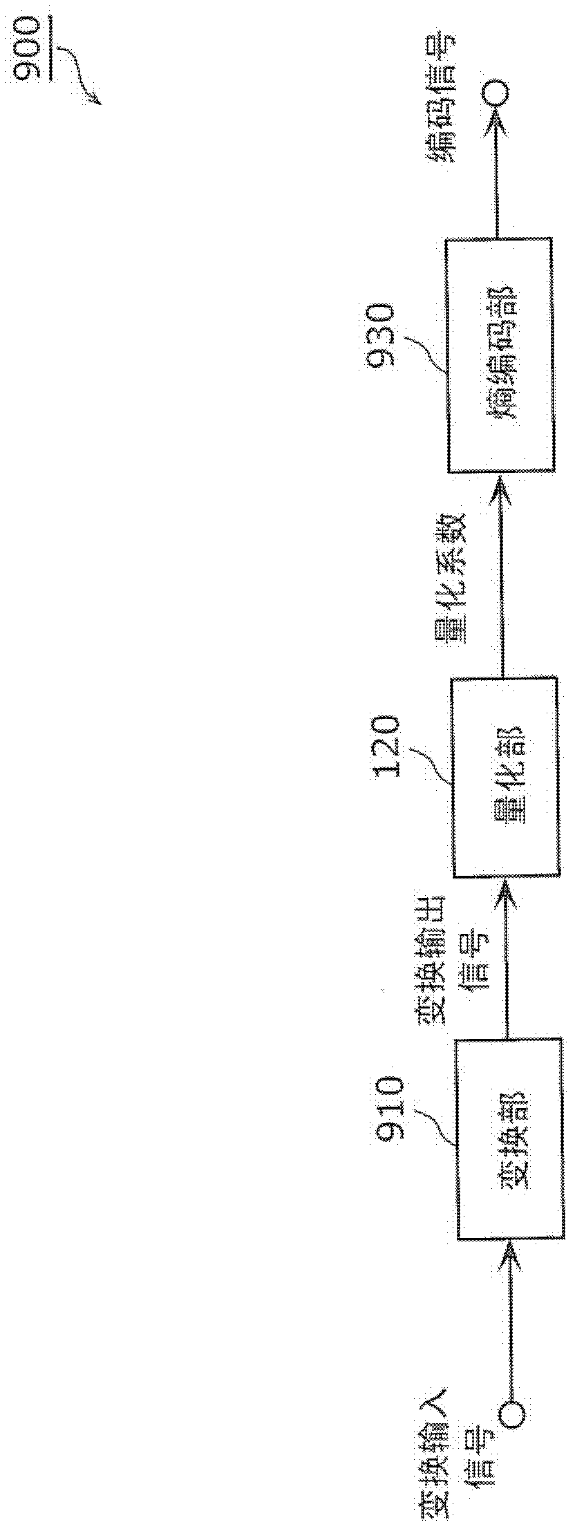
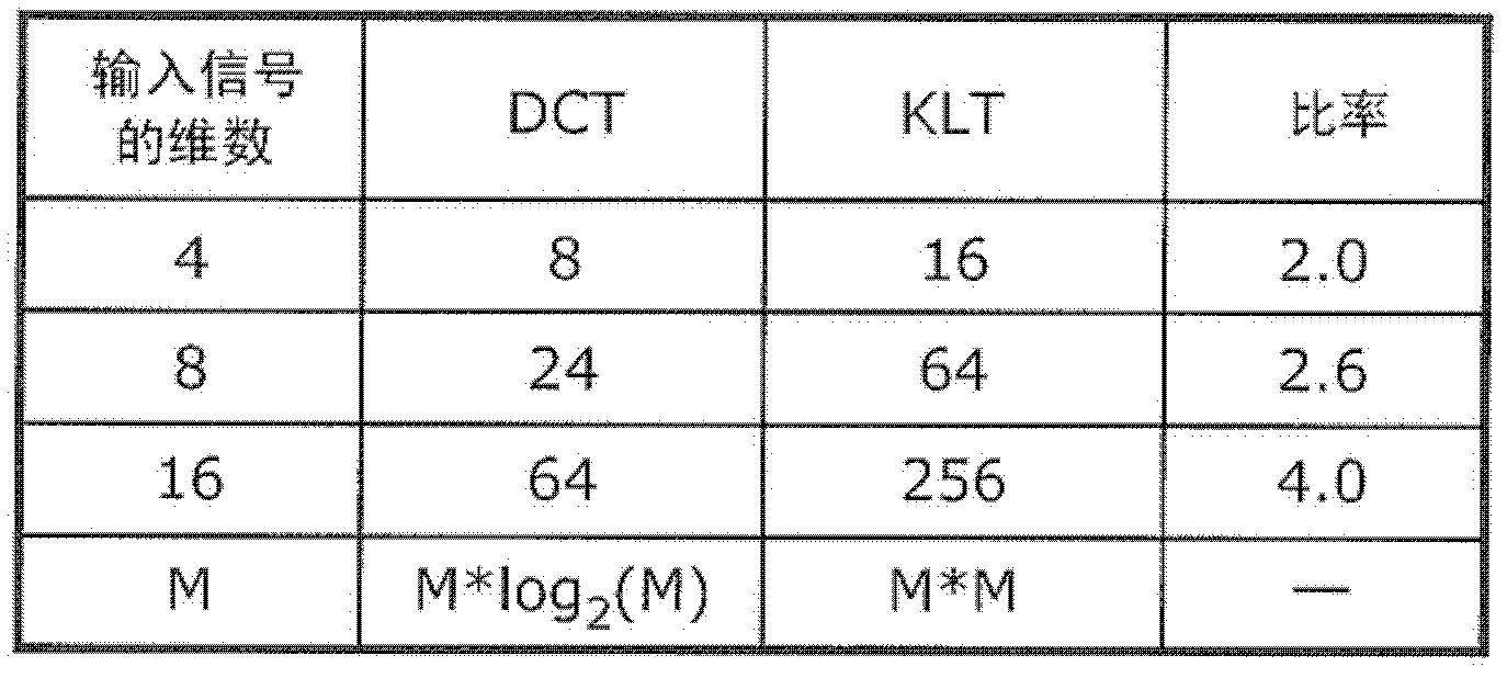
[0123] The encoding device of the first embodiment is an encoding device that generates a coded signal by encoding an input signal, and is characterized by including: a conversion unit that generates a converted output signal from the input signal by performing conversion processing; and quantizes the converted output signal A quantization unit that generates quantized coefficients; and an encoding unit that generates coded signals by compression coding the quantized coefficients and transform coefficients. The transform unit uses transform coefficients based on the signal based on the input signal and based on the statistical characteristics of the set of transform target signals that are the target of the transform process to determine the coefficients of the square matrix to transform the transform target signal, and the encoding unit calculates The difference between the element included in the transform coefficient or the inverse transform coefficient used in the inverse tr...
Embodiment approach 2
[0323] The decoding device according to the second embodiment is a decoding device that generates a decoded signal by decoding a coded signal, and is characterized in that the coded signal includes coded quantized coefficients after compression coding and included in the transformation process performed when generating the coded signal. The difference between the element in the transform coefficient used in and the specified value. The decoding device according to the second embodiment includes: a decoding unit that generates decoded quantized coefficients and inverse transform coefficients by decoding a coded signal; an inverse quantization unit that generates decoded transformed output signals by inverse quantization of decoded quantized coefficients; and using inverse transform The coefficient is subjected to an inverse transform process, which is a process opposite to the transform process performed on the encoding side, and an inverse transform unit that generates a decoded...
Embodiment approach 3
[0450] By recording a program for realizing the structure of the moving picture encoding method or the moving picture decoding method shown in each of the above embodiments into a storage medium, the processing shown in each of the above embodiments can be easily implemented in an independent computer system. . The storage medium is a magnetic disk, optical disk, magneto-optical disk, IC card, semiconductor memory, etc., as long as it is a medium capable of recording programs.
[0451] Furthermore, application examples of the moving picture coding method and the moving picture decoding method shown in each of the above-mentioned embodiments and a system using them will be described here.
[0452] Figure 32 It is a diagram showing the overall structure of a content supply system ex100 that realizes content distribution services. The communication service providing area is divided into desired sizes, and base stations ex107 to ex110 as fixed wireless stations are installed in each ...
PUM
 Abstract
Description
Claims
Application Information
 - R&D
- Intellectual Property
- Life Sciences
- Materials
- Tech Scout
- Unparalleled Data Quality
- Higher Quality Content
- 60% Fewer Hallucinations
Browse by: Latest US Patents, China's latest patents, Technical Efficacy Thesaurus, Application Domain, Technology Topic, Popular Technical Reports.
© 2025 PatSnap. All rights reserved.Legal|Privacy policy|Modern Slavery Act Transparency Statement|Sitemap|About US| Contact US: help@patsnap.com


