Encoding method, decoding method, encoding device and decoding device

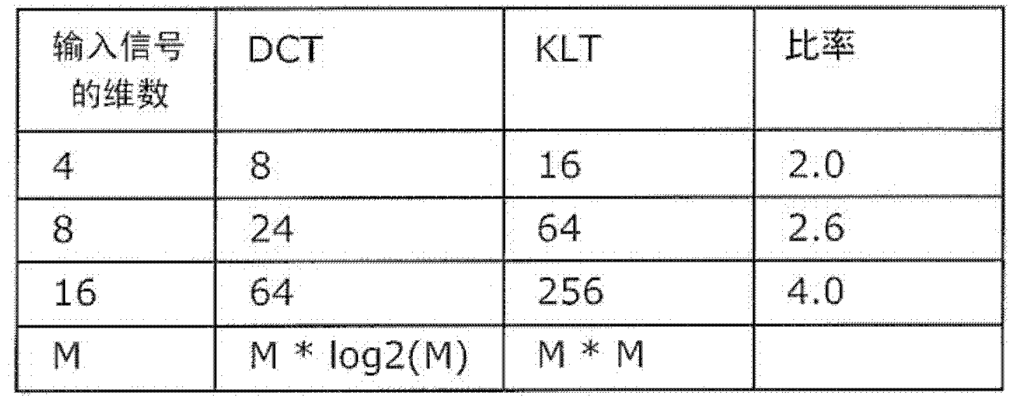
A technology of encoding method and decoding method, which is applied in the direction of code conversion, television, electrical components, etc., can solve the problems of large amount of computation, large amount of transformation coefficient data, difficulty in using KLT, etc., and achieve the effect of suppressing increase and improving coding efficiency

Inactive Publication Date: 2012-05-23
PANASONIC CORP
View PDF0 Cites 0 Cited by
  • Summary
  • Abstract
  • Description
  • Claims
  • Application Information

AI Technical Summary

Problems solved by technology

[0024] As described above, in the transformation using a transformation matrix composed of transformation coefficients calculated based on the statistical properties of the input signal such...

Method used


Image

  • Encoding method, decoding method, encoding device and decoding device
  • Encoding method, decoding method, encoding device and decoding device
  • Encoding method, decoding method, encoding device and decoding device

Examples


Embodiment approach 1

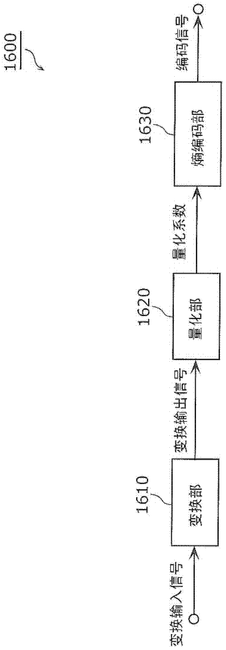
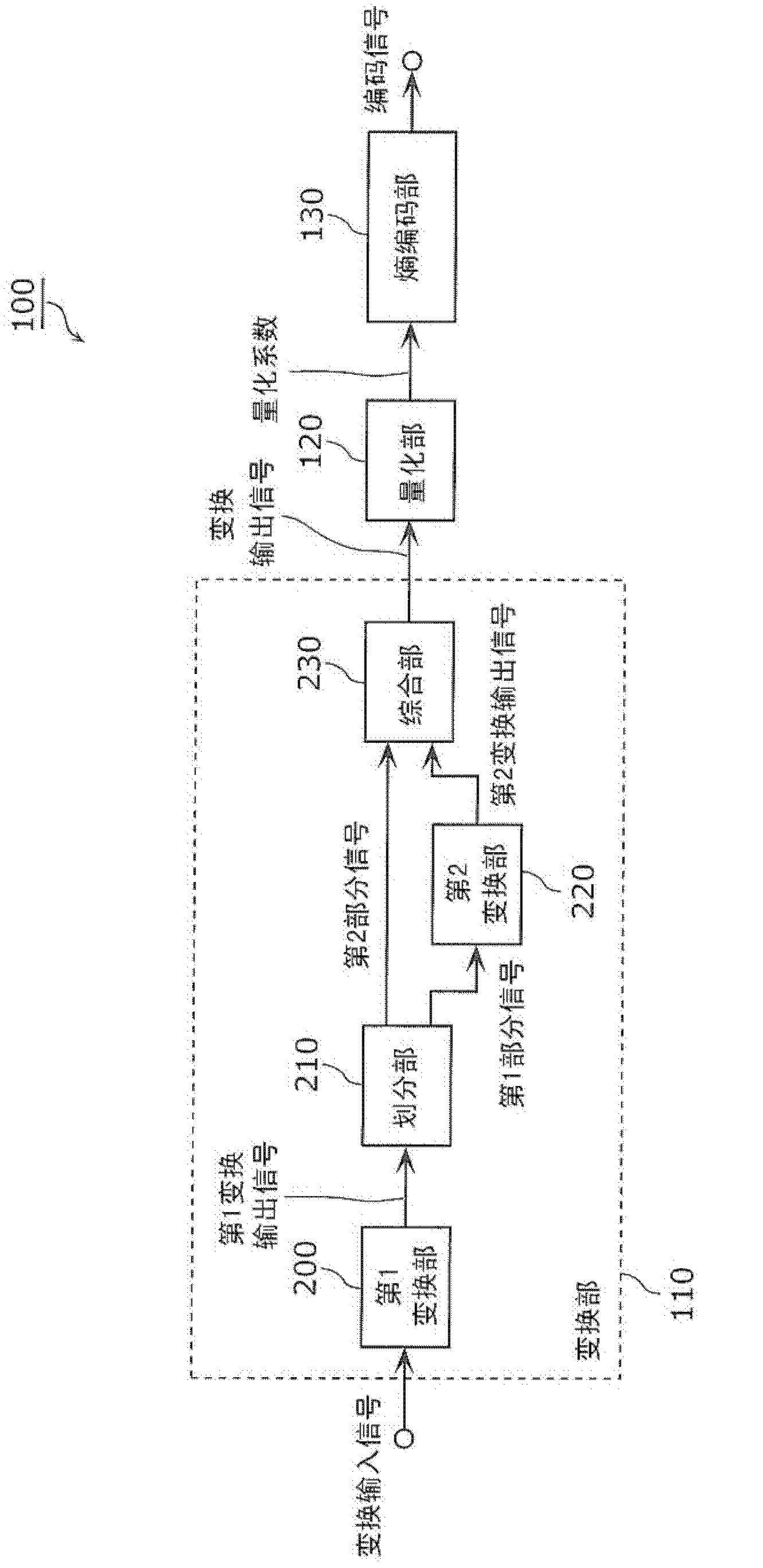
[0139] The coding device according to Embodiment 1 of the present invention includes a transform unit that transforms an input signal to generate a transformed output signal, a quantization unit that generates a quantized coefficient by quantizing the transformed output signal, and a quantized coefficient generated by entropy coding the quantized coefficient. The entropy encoded portion of the signal. Furthermore, the transform unit includes a first transform unit that generates a first transformed output signal by performing a first transform on an input signal using a first transform matrix composed of first transform coefficients, and a first transformed output signal that is a part of the first transformed output signal. The first partial signal is subjected to the second transformation using the second transformation matrix composed of the second transformation coefficients to generate the second transformation output signal, and the first transformation output signal incl...

Embodiment approach 2

[0200] A decoding device according to Embodiment 2 of the present invention includes an entropy decoding unit that generates a decoded quantization coefficient by entropy decoding a coded signal, an inverse quantization unit that generates a decoded transformed output signal by inverse quantizing the decoded quantization coefficient, and an entropy decoding unit that generates a decoded transformed output signal by An inverse transform unit that inversely transforms the transform output signal to generate a decoded signal. Further, the inverse transform unit includes a second inverse transform for generating a first decoded partial signal by performing a second inverse transform on a second decoded transformed output signal that is a part of the decoded transformed output signal using a second inverse transform matrix composed of second inverse transform coefficients. 2 inverse transform units, and using the first inverse transform method for the first decoded transformed outpu...

Embodiment approach 3

[0252] The encoding device and encoding method according to Embodiment 3 of the present invention include a conversion unit and a conversion method for converting audio data, still image data, moving image data, and other signals to be encoded by combining multiple types of transforms. The encoding device and encoding method according to Embodiment 3 of the present invention are characterized in that a prediction error signal which is a difference between an encoding target signal (input signal) and a prediction signal is subjected to two-stage conversion as a converted input signal.

[0253] Figure 17 It is a block diagram showing an example of the configuration of the encoding device 500 according to Embodiment 3 of the present invention. Such as Figure 17 As shown, the encoding device 500 according to Embodiment 3 of the present invention includes a subtracter 505, a transform unit 510, a quantization unit 120, an entropy encoding unit 130, an inverse quantization unit 5...


PUM


Abstract

Disclosed is an encoding method including a transform step (S110a) for transforming an input signal; a quantization step (S120) for quantizing the transform output signal; and an entropy encoding step (S130) for entropy encoding quantized coefficients. The transform step (S110a) includes a first transform step (S112) for generating the first transform output signal by way of performing a first transform on the input signal using a first transform coefficient; and a second transform step (S116a) for generating a second transform output signal by way of performing a second transform using a second transform coefficient on a first partial signal which is a portion of the first transform output signal, and outputting a transform output signal which includes the generated second transform output signal and a second partial signal which is the portion of the first transform output signal excluding the first partial signal. In the second transform step (S116a), either the range of the first transform output signal for the second transform as the first partial signal, and/or the second transform coefficient, is temporally or spatially adaptively determined.

Description

technical field [0001] The present invention relates to an encoding method for encoding audio, still images, and moving images, and more particularly, to an encoding method including transform processing for transforming an input signal from a time-space domain to a frequency domain. Background technique [0002] In order to compress audio data and video data, many audio coding standards and video coding standards have been developed. Examples of video encoding standards include the ITU-T standard called H.26x and the ISO / IEC standard called MPEG-x. The latest video encoding standard is a standard called H.264 / MPEG-4AVC. [0003] figure 1 It is a block diagram showing the configuration of a conventional encoding device 1600 . Such as figure 1 As shown, the encoding device 1600 includes a transform unit 1610, a quantization unit 1620, and an entropy encoding unit 1630, and encodes audio data and video data at a low bit rate. [0004] The conversion unit 1610 generates a ...

Claims


Application Information

Patent Timeline
IPC IPC(8): H03M7/30H04N7/30H04N7/32
CPCH04N7/26079H04N7/26702H04N7/26095H04N19/00775H04N19/00109H04N7/26106H04N7/26101H04N19/0009H04N19/00084H04N19/00296H04N19/00951H04N7/2625H04N19/00478H04N7/30H04N19/122H04N19/124H04N19/129H04N19/18H04N19/42H04N19/60H04N19/91H04N19/13H04N19/132
Inventor 柴原阳司西孝启笹井寿郎谷川京子M·纳罗施克V·德吕容S·维特曼
Owner PANASONIC CORP
Why Eureka
Try Eureka