Check patentability & draft patents in minutes with Patsnap Eureka AI!

Swing mechanism for driving part of machine tool to rotate

A technology of slewing mechanism and machine tool, which is applied in the direction of metal processing machinery parts, manufacturing tools, metal processing equipment, etc. It can solve the problems of increasing cost expenditure, occupying space, affecting positioning accuracy, etc., and achieves the effect of precisely controlling the rotation angle

Pending Publication Date: 2021-12-17
SANJET INT
View PDF0 Cites 0 Cited by
  • Summary
  • Abstract
  • Description
  • Claims
  • Application Information

AI Technical Summary

Problems solved by technology

[0003] It is true that the above-mentioned slewing mechanism changes the linear motion into a rotation mode, so as to realize the purpose of controlling the rotation of the components, but the backlash problem in the meshing relationship between the gear and the rack affects the positioning accuracy of the components when they stop after rotation; Otherwise, the above-mentioned slewing mechanism must be equipped with a pressure cylinder structure at both ends of the rack, which not only increases the cost but also takes up space.

Method used


Image

  • Swing mechanism for driving part of machine tool to rotate
  • Swing mechanism for driving part of machine tool to rotate
  • Swing mechanism for driving part of machine tool to rotate

Examples


Embodiment Construction

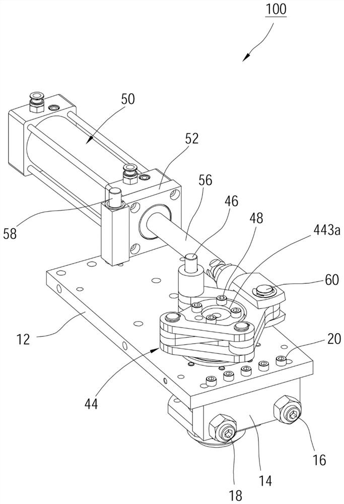
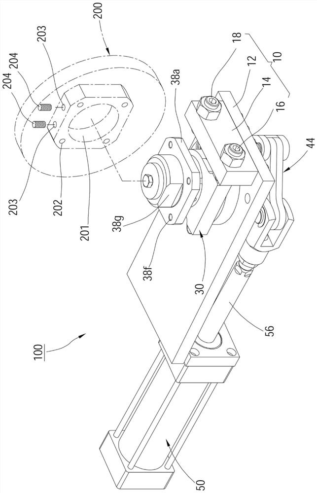
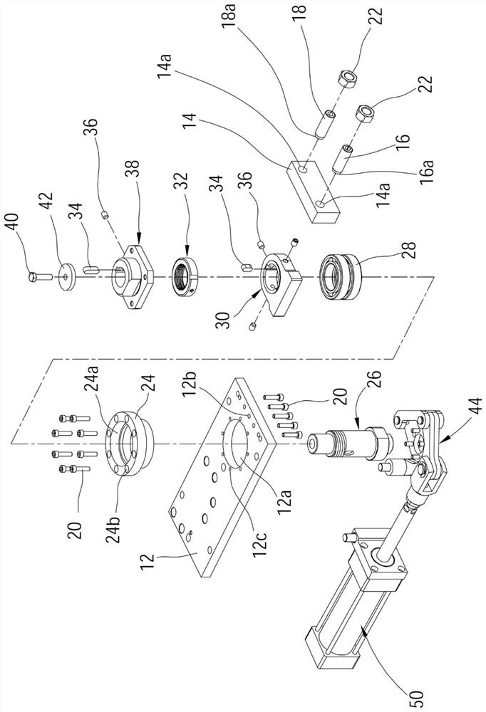
[0092] In order to illustrate the present invention more clearly, a preferred embodiment is given and described in detail with accompanying drawings as follows. Please refer to Figure 1 to Figure 4 As shown, the rotary mechanism 100 of a preferred embodiment of the present invention is used to drive the parts of the machine tool to rotate. The aforementioned parts are, for example, the tool changing arm of the automatic tool changing mechanism or a kind of changing plate, but not limited thereto. The rotary mechanism 100 of this embodiment includes a base 10 , a bearing seat 24 , a rotating shaft 26 , at least one bearing 28 , a block 30 , a locking nut 32 , a connecting seat 38 , a link mechanism 44 , and a driving mechanism 50 . Hereby explain one by one as follows.

[0093]The base 10 includes a solid rigid member 12 , a coupling block 14 , a first adjustment piece 16 and a second adjustment piece 18 . The rigid member 12 has a circular opening 12a, a plurality of throug...


PUM


Abstract

The invention discloses a swing mechanism for driving a part of a machine tool to rotate. The swing mechanism comprises a base, a rotating shaft, a driving mechanism and a connecting rod mechanism, wherein, the rotating shaft penetrates through the base and can rotate in place, and one end of the rotating shaft is used for being connected with the part; and the driving mechanism comprises a push-pull rod which can bear acting force to move back and forth, and the push-pull rod drives the rotating shaft to rotate through the connecting rod mechanism, and therefore, the rotating angle of the rotating shaft can be accurately controlled.

Description

technical field [0001] The present invention relates to processing tools; in particular, it refers to a rotary mechanism for driving the parts of the machine tool to rotate. Background technique [0002] In the field of machine tools, it is often necessary to actuate and rotate specific components, such as a tool changing arm of an automatic tool changing mechanism or a type of changing disc. The known mechanism for performing the aforementioned actions is a rotary mechanism that includes a rotating shaft, a gear, and a rack. When it is a part of the rotating shaft, it can drive the components combined at one end of the rotating shaft to generate corresponding rotation. [0003] It is true that the above-mentioned slewing mechanism changes the linear motion into a rotation mode, so as to realize the purpose of controlling the rotation of the components, but the backlash problem in the meshing relationship between the gear and the rack affects the positioning accuracy of the...

Claims


Application Information

Patent Timeline
IPC IPC(8): B23Q3/155
CPCB23Q3/155B23Q3/1554
Inventor 张庆三
Owner SANJET INT
Features
  • R&D
  • Intellectual Property
  • Life Sciences
  • Materials
  • Tech Scout
  • Unparalleled Data Quality
  • Higher Quality Content
  • 60% Fewer Hallucinations
Learn More