Injection molding machine with double injection molding ports

A technology of injection molding machine and double injection molding, which is applied in the direction of grain processing, etc., can solve the problems of reducing processing efficiency, inability to filter raw material particles, single function, etc., and achieve the effect of improving processing efficiency and facilitating recycling and reuse

Pending Publication Date: 2021-12-17
许强程
View PDF16 Cites 0 Cited by
  • Summary
  • Abstract
  • Description
  • Claims
  • Application Information

AI Technical Summary

Problems solved by technology

[0004] 1. The existing double-injection injection molding machine usually has two barrels in the same direction, and each barrel is equipped with a separate hopper. During the processing, the two hoppers need to be fed separately, and the two barrels are It works synchronously when working. If the feeding is not timely, the lack of material in the barrel will affect the processing efficiency, and the frequent addition of materials to the two hoppers will reduce the processing efficiency;
[0005] 2. If large raw material particles enter the barrel, it will cause uneven melting of raw materials and blockage of the injection molding port. The traditional hopper is only responsible for storing materials and cannot filter raw material particles. It has a single function

Method used


Image

  • Injection molding machine with double injection molding ports
  • Injection molding machine with double injection molding ports
  • Injection molding machine with double injection molding ports

Examples


Embodiment Construction

[0043] The following will clearly and completely describe the technical solutions in the embodiments of the present invention with reference to the accompanying drawings in the embodiments of the present invention. Obviously, the described embodiments are only some, not all, embodiments of the present invention. Based on the embodiments of the present invention, all other embodiments obtained by persons of ordinary skill in the art without making creative efforts belong to the protection scope of the present invention.

[0044] see Figure 1 to Figure 9 , the present invention provides a technical solution:

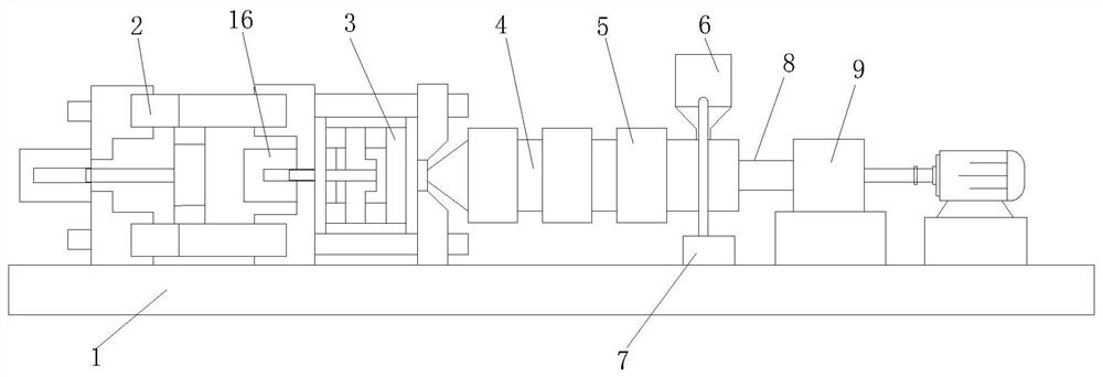
[0045] An injection molding machine with double injection ports, comprising a base 1, a mold clamping device 2 is fixedly installed on one side of the upper outer surface of the base 1, and a mold 3 is fixedly installed on one side of the outer surface of the mold clamping device 2, the mold The outer surface of one side of the barrel 3 is movably connected with a barrel...


PUM


Abstract

The invention discloses an injection molding machine with double injection molding ports. The injection molding machine comprises a base, a mold closing device is fixedly installed on one side of the outer surface of the upper end of the base, a mold is fixedly installed on the outer surface of one side of the mold closing device, charging barrels are movably connected to the outer surface of one side of the mold, and a heater is fixedly installed on the outer surface of each charging barrel; and a hopper is fixedly installed at the upper end of the sides, away from the mold, of the outer surfaces of the charging barrels, a screw rod is installed on one side of each charging barrel in an embedded mode, a hydraulic cylinder is fixedly connected to one side of each screw rod, and a flow dividing pipe is fixedly installed at the lower end of the hopper. The injection molding machine uses one hopper to feed the two charging barrels, the working efficiency is improved, meanwhile, the hopper can filter and crush raw materials, so that larger particles are filtered or decomposed into small particles in the hopper, the larger material particles are prevented from entering the charging barrels, and if the larger particles cannot be decomposed, the larger particles are discharged outwards so as to be recycled.

Description

technical field [0001] The invention relates to the technical field of injection molding machines, in particular to an injection molding machine with double injection ports. Background technique [0002] Injection molding machines have the ability to form plastic products with complex shapes, precise dimensions, or dense textures with metal inserts at one time, and are widely used in national defense, electromechanical, automobiles, transportation, building materials, packaging, agriculture, culture, education, health and people's daily life in all areas. Today, with the rapid development of the plastics industry, injection molding machines play an important role in terms of quantity and variety, and thus become one of the fastest growing and most produced models of plastic machinery; [0003] In the process of realizing the present invention, the inventor found that at least the following problems in the prior art have not been solved: [0004] 1. The existing double-inje...

Claims


Application Information

Patent Timeline
Patent Type & Authority Applications(China)
IPC IPC(8): B29C45/18B29B13/00B29B13/10B02C18/10B02C18/18B02C18/24B02C23/16
CPCB29C45/18B29B13/00B29B13/10B02C18/10B02C18/18B02C18/24B02C23/16B02C2023/165
Inventor 许强程程良
Owner 许强程
Why Eureka
Try Eureka