

Scroll compressor
A technology of scroll compressors and scroll disks, applied in the direction of rotary piston machinery, rotary piston pumps, mechanical equipment, etc., can solve the problems of increased specific volume, aggravated suction loss, heating, etc.
- Summary
- Abstract
- Description
- Claims
- Application Information
AI Technical Summary
Problems solved by technology
Method used
Image

Examples
Embodiment Construction
[0047] Next, according to an embodiment shown in the drawings, the scroll compressor of this embodiment will be described in detail.
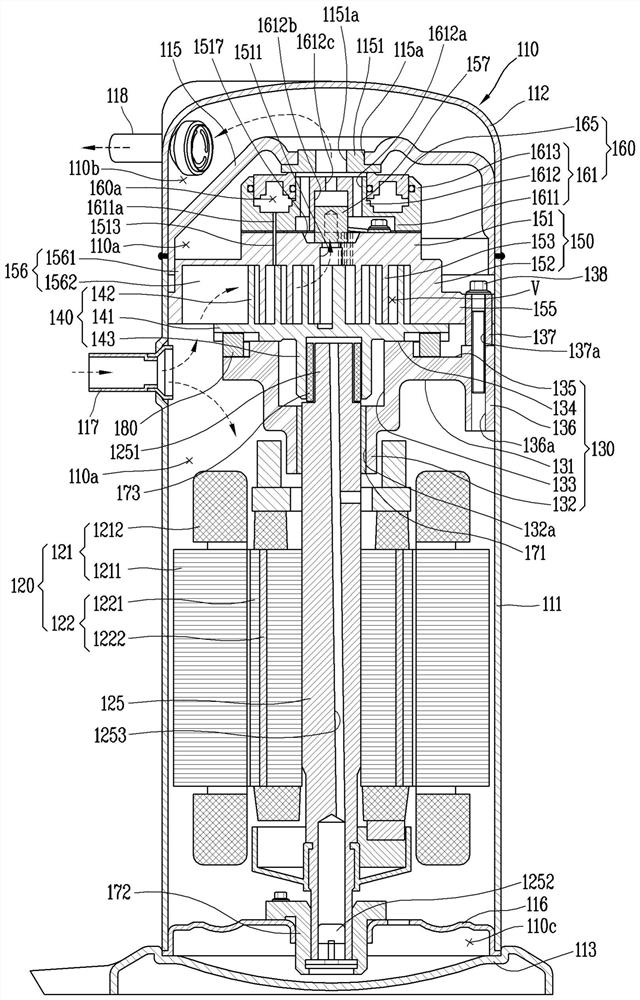
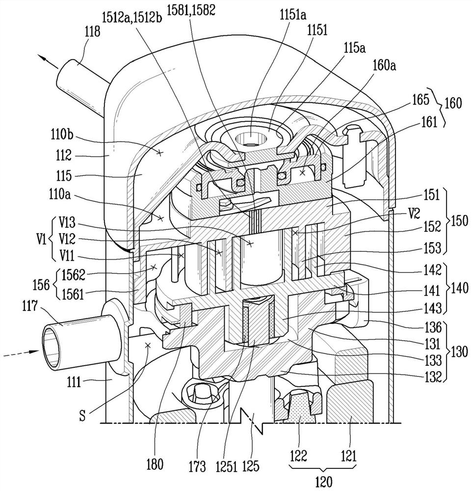
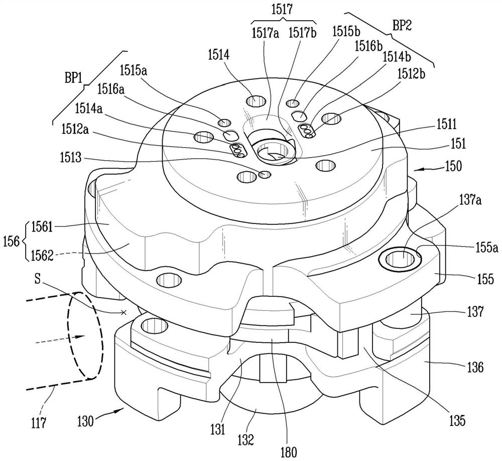
[0048] figure 1 It is a longitudinal sectional view showing the inside of the capacity variable scroll compressor of this embodiment, figure 2 Yes figure 1 A cut-away perspective view of the interior of a scroll compressor, image 3 is in figure 2 A perspective view showing the assembly of the compression section in the scroll compressor.
[0049] refer to figure 1 and figure 2 , in the scroll compressor of this embodiment, a driving motor 120 is provided on the lower half of the housing 110, and a main frame 130, an orbiting scroll 140, and a non-orbiting scroll are arranged in sequence on the upper side of the driving motor 120. The turntable 150 and the back pressure chamber assembly 160 . Generally, the driving motor 120 constitutes an electric part, and the main frame 130, the orbiting scroll 140, the non-orbiting scroll 150, and...
PUM
 Abstract
Description
Claims
Application Information