Method for assembling trigger component of submachine gun

A technology for a submachine gun and a trigger, applied in the field of submachine guns, can solve the problems of increasing the failure rate of submachine guns, difficult to master the assembly method, and dare not to easily decompose iron-resistant parts, etc., and achieves good economic and social benefits, convenient and fast assembly operation, and good promotion. and practical value

Active Publication Date: 2021-12-17
CHONGQING JIANSHE IND GRP
View PDF12 Cites 2 Cited by
  • Summary
  • Abstract
  • Description
  • Claims
  • Application Information

AI Technical Summary

Problems solved by technology

[0003] At present, the assembly of submachine gun trigger parts is installed by hand. It is necessary to put the iron resistance spring into the spring hole of the iron resistance spring at the lower part of the single-shot iron resistance, and then put the outer torsion arm of the trigger spring with a parallel double-torsion spring structure into the single-shot Send out the outer circle of the cylinder on the side of the resistance iron, and then align the resistance iron spring with the resistance spring hole on the trigger, and make the inner torsion arm of the trigger spring straddle the trigger so that the second outer torsion arm overlaps the trigger. On the inner slot, finally pass the assembly sleeve through the assembly sleeve installation hole of the trigger spring, the assembly sleeve installation hole on one side of the trigger, the assembly sleeve installation hole of the single sear and the assembly sleeve installation hole on the other side of the trigger, thus completing Installation; the free-hand tool-free assembly process of the above-mentioned trigger parts is extremely laborious and difficult to operate, especially when the assembly sleeve is under the action of spring force, it needs to pass through the mounting hole of the upper assembly sleeve of the trigger that is the same as the outer diameter of the small end of the assembly sleeve. There are three layers of holes in the upper assembly sleeve installation hole of the single-engine sear and the assembly sleeve installation hole on the other side of the trigger. It is very difficult to assemble by hand; It is relatively shallow, and it is very easy to slip off from the stop hole of the trigger during the assembly process when the stop iron spring is aligned with the stop iron spring limit hole on the trigger, so that the assembly process will be wasted, or even if it is installed, the stop iron will fail The posture of the spring is not correct, and the normal function cannot be realized, which brings great difficulties and burdens to the assembly work of the assembler. Because the assembly method is difficult to master, users such as military police dare not easily disassemble it in daily maintenance operations. Iron-sealing components can easily lead to an increase in the failure rate of submachine guns due to improper maintenance

Method used


Image

  • Method for assembling trigger component of submachine gun
  • Method for assembling trigger component of submachine gun
  • Method for assembling trigger component of submachine gun

Examples


Embodiment Construction

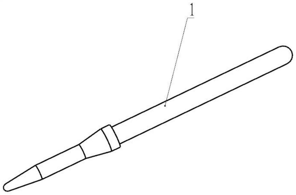
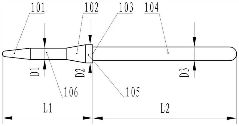
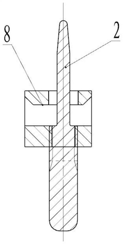
[0038] Below in conjunction with the accompanying drawings the present invention is further described, in the accompanying drawings, 1-replacement pin, 2-blocking iron spring limit lever, 3-trigger, 4-trigger spring, 5-single-shot sear, 6-blocking iron spring, 7-assembly sleeve, 8-block iron spring limit base; 101-conical tip, 102-conical guide section, 103-right angle positioning shoulder, 104-assembly sleeve installation section, 105-second transition section, 106-first transition section, 201-limit guide section, 202-limit section, 203-external thread connection section, 301-installation hole 1 of upper assembly sleeve on trigger, 302-installation hole 2 of upper assembly sleeve on trigger, 303-trigger Limiting hole of the upper resistance iron spring, 304-process hole of the upper resistance iron spring of the trigger, 401-inner torsion arm of the trigger spring, 402-inner hole of the cylindrical spiral of the trigger spring, 403-the first outer torsion arm of the trigger s...


PUM


Abstract

The invention discloses a method for assembling a trigger component of a submachine gun. The trigger component of the submachine gun can be conveniently and rapidly assembled. The method comprises the following steps: S1, preparing a substitute pin, a sear spring limiting rod and a sear spring limiting base; S2, mounting the sear spring limiting base and the sear spring limiting rod; S3, installing an assembling sleeve; and S4, assembling the trigger component.

Description

technical field [0001] The invention relates to the technical field of submachine guns, in particular to a method for assembling a trigger part of a submachine gun. Background technique [0002] In order to improve the convenience of submachine gun transmitter mechanism assembly, it is necessary to pre-assemble the trigger, single shot sear, trigger spring and sear spring of the submachine gun into a trigger part through the assembly sleeve. [0003] At present, the assembly of submachine gun trigger parts is installed by hand. It is necessary to put the iron resistance spring into the spring hole of the iron resistance spring at the lower part of the single-shot iron resistance, and then put the outer torsion arm of the trigger spring with a parallel double-torsion spring structure into the single-shot Send out the outer circle of the cylinder on the side of the resistance iron, and then align the resistance iron spring with the resistance spring hole on the trigger, and ma...

Claims


Application Information

Patent Timeline
Patent Type & Authority Applications(China)
IPC IPC(8): F41A11/00
CPCF41A11/00
Inventor 熊长林陈华荣唐程远田瑜王希阔王飞开友叶李良刚周杰黄建
Owner CHONGQING JIANSHE IND GRP
Why Eureka
Try Eureka