
Eureka
For R&D, Eureka makes reading and utilizing patents & technical documents easy.
Eureka AIR
Designed for self-driven R&D workflows. Generate viable solutions, solve complex R&D challenges, empower your innovation with AI.

Eureka Materials
Designed for material experts only. Revolutionize your material R&D, from search, analyze, to developing new materials.

TechResearch
Generate reliable direction feasibility study reports for your R&D in just a few steps.

TechSeek
Discover and master advanced knowledge NOW. Basics, ideas, possibilities, all at once.

TechMind
As an expert in R&D Theories, TechMind can generates customized viable solutions instantly.

TechRisk
Analyze your overall solution with one click, know your potential R&D risks in advance.

TechMonitor
Get weekly tech updates, stay abreast of the latest tech innovations and key insights.
Adjustable constant force mechanism
A technology for regulating mechanism and force, applied in the direction of control/regulation system, mechanical pressure/force control, instrument, etc., can solve the problems of high processing accuracy, poor interchangeability, high processing accuracy requirements, etc., to reduce friction loss, The effect of improving the service life and avoiding the reduction of precision
- Summary
- Abstract
- Description
- Claims
- Application Information
AI Technical Summary
Problems solved by technology
Method used
Image

Examples
Embodiment 1
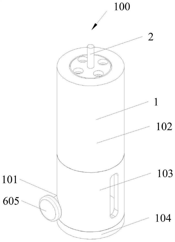
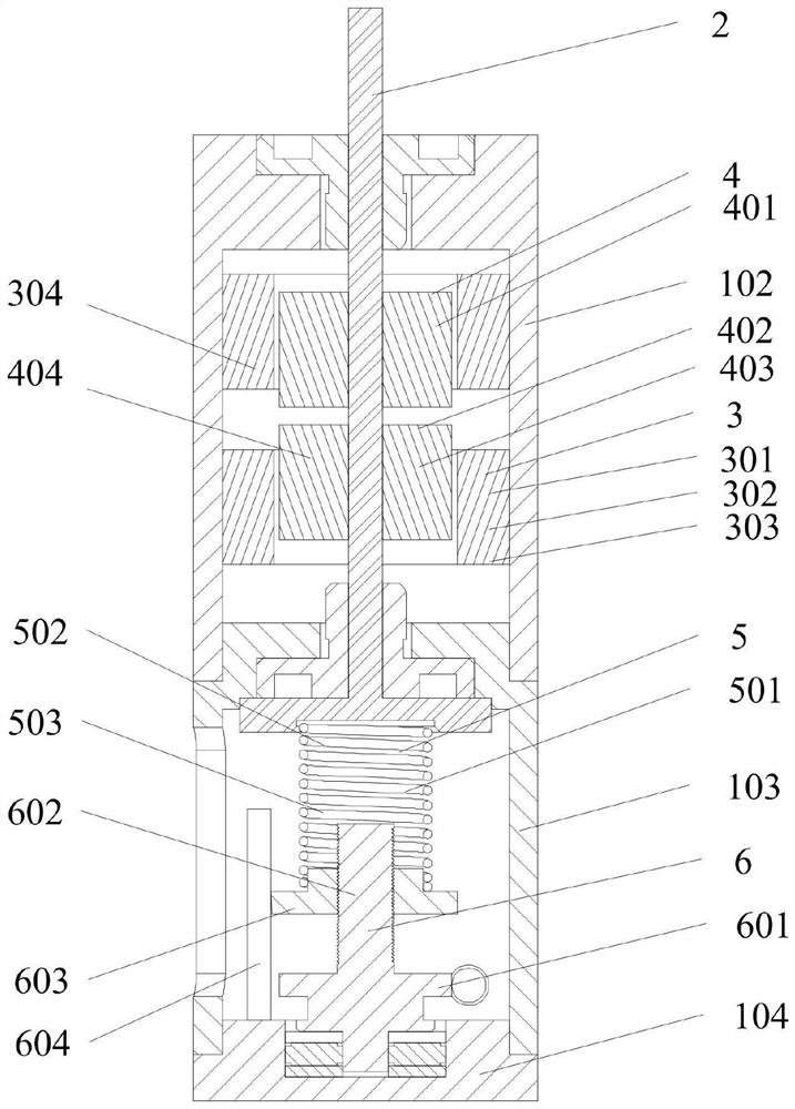
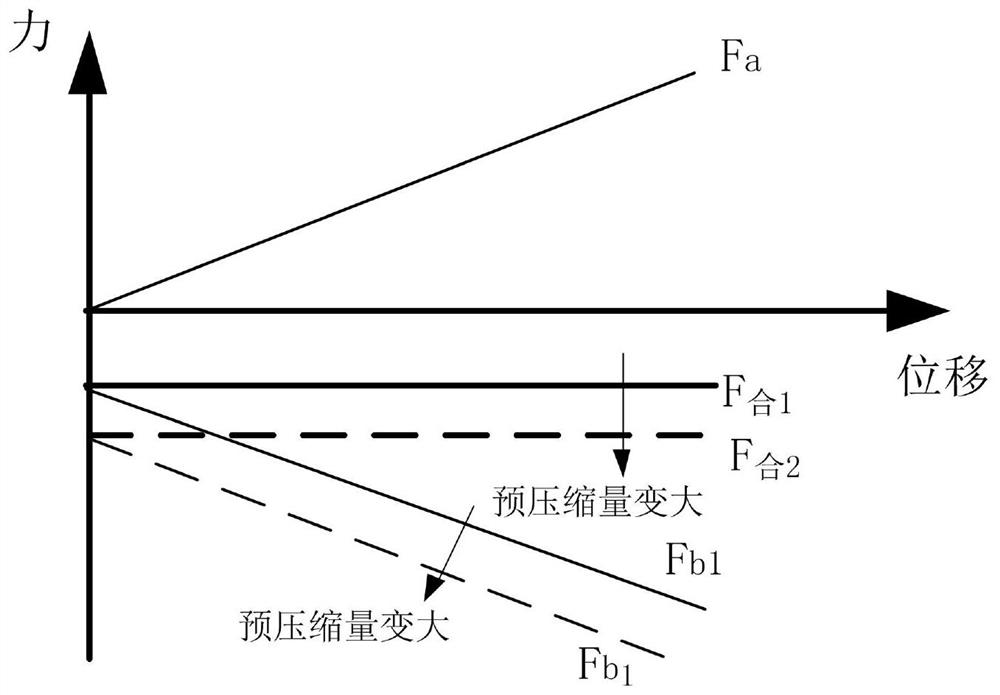
[0038] Such as Figure 1-8 As shown, the present embodiment provides one, including a casing 1, an output shaft 2, an annular stator 3, an annular mover 4 and a positive stiffness mechanism 5, the annular stator 3 is sleeved in the casing 1 and is fixedly connected with the casing 1, and the annular movable The sub 4 is sleeved in the annular stator 3 and has a gap with the annular stator 3. The output shaft 2 is fixedly connected with the annular mover 4 and the positive stiffness mechanism 5. The output shaft 2 is arranged inside the casing 1 and is connected with the casing 1 in rotation. The output The shaft 2 can move along the axis direction of the output shaft 2, and the annular mover 4 can provide the first force F for the output shaft 2 under the action of the magnetic field in the inner cavity of the annular stator 3 a , the positive stiffness mechanism 5 can provide the second force F for the output shaft 2 b , the first force F a with the second force F b direct...
Embodiment 2
[0080] Such as Figure 1-12 As shown, in this embodiment, the annular stator 3 is the third coil 302, the annular mover 4 is the first permanent magnet 402, the magnetization direction of the first permanent magnet 402 is parallel to the axial direction of the output shaft 2, and the third coil 302 The direction of the magnetic field at the center is opposite to the magnetization direction of the first permanent magnet 402 after the current is applied. Such as Figure 9-11 As shown, the first permanent magnet 402 is axially magnetized and the direction is downward, and the current direction of the third coil 302 is counterclockwise (looking down at the first coil 301 from top to bottom). According to the ampere current model, the first permanent magnet 402 Equivalent to radius r m The first annular permanent magnet 10 and the radius R m The second annular permanent magnet 11, the first annular permanent magnet 10 is opposite to the magnetization direction of the first perma...
Embodiment 3
[0089] Such as Figure 1-13 As shown, in this embodiment, the annular stator 3 is the second permanent magnet 303, the annular mover 4 is the third permanent magnet 403, and the magnetic field directions of the second permanent magnet 303 and the third permanent magnet 403 are parallel to the direction of the output shaft 2. In the axial direction, the magnetic field directions of the second permanent magnet 303 and the third permanent magnet 403 are the same. The analysis method of the electromagnetic force that the third permanent magnet 403 receives in the magnetic field of the second permanent magnet 303 is the same as that in Embodiment 2. Within a certain range where the third permanent magnet 403 deviates from the midplane 9 of the second permanent magnet 303, the electromagnetic force that the third permanent magnet 403 receives in the magnetic field of the second permanent magnet 303 is the same as the displacement direction and is linear. Such as Figure 13 shown, ...
PUM
 Abstract
Description
Claims
Application Information
 - R&D Engineer
- R&D Manager
- IP Professional
- Industry Leading Data Capabilities
- Powerful AI technology
- Patent DNA Extraction
Browse by: Latest US Patents, China's latest patents, Technical Efficacy Thesaurus, Application Domain, Technology Topic, Popular Technical Reports.
© 2024 PatSnap. All rights reserved.Legal|Privacy policy|Modern Slavery Act Transparency Statement|Sitemap|About US| Contact US: help@patsnap.com