
Dimming circuit

A dimming circuit and dimming signal technology, applied in the direction of electrical components, etc., can solve the problems of dimming dead zone, failure to generate, and difficulty in analog signal processing, etc., to improve control accuracy, avoid flickering lights, and simple and flexible adjustment methods Effect

Active Publication Date: 2021-12-17
深圳赫飞物联科技有限公司
View PDF5 Cites 0 Cited by
  • Summary
  • Abstract
  • Description
  • Claims
  • Application Information

AI Technical Summary

Problems solved by technology

[0006] However, when the PWM signal is directly generated by chopping to adjust the brightness of the lamp, it is easy to encounter the problem of dimming dead zone, that is, when the duty cycle of the PWM signal changes, the number of power switching cycles in one cycle of the PWM signal does not change No change, resulting in the output current not responding to the dimming action, that is, the dimming curve is not linear enough, and the actual experience is not good
In addition, when an analog voltage is used to adjust the brightness, etc., the process of transmitting the analog signal to the dimming interface of the LED driver chip is susceptible to external interference, and there may also be a problem of insufficient dimming depth. Among them, the dimming depth The disadvantage is that for application scenarios that require extremely low brightness, it is relatively difficult for the system to process tiny analog signals (and the small signals themselves are more likely to be interfered), which may result in the inability to generate a relatively low output current

Method used


Image

  • Dimming circuit
  • Dimming circuit
  • Dimming circuit

Examples


Embodiment Construction

[0055] The core of the present invention is to provide a dimming circuit, which is less susceptible to external interference, and the adjustment method of the data frame is simpler and more flexible, and effectively avoids flickering lights, which can improve the control accuracy of the light brightness.

[0056] In order to make the purpose, technical solutions and advantages of the embodiments of the present invention clearer, the technical solutions in the embodiments of the present invention will be clearly and completely described below in conjunction with the drawings in the embodiments of the present invention. Obviously, the described embodiments It is a part of embodiments of the present invention, but not all embodiments. Based on the embodiments of the present invention, all other embodiments obtained by persons of ordinary skill in the art without making creative efforts belong to the protection scope of the present invention.

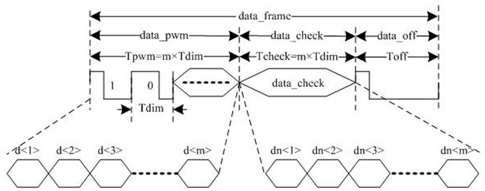
[0057] Please refer to figure 1 , ...


PUM


Abstract

The invention discloses a dimming circuit, which comprises a demodulation module, a verification module and a dimming signal generation module. A control signal for a driving module is transmitted in a mode of transmitting a data frame, so that the driving module is controlled to act on the basis of the control signal to change the current passing through a lamp, and the brightness of the lamp is further changed. Compared with an analog signal, the data frame form is not easily interfered by the outside. Compared with a PWM signal obtained through chopping, the adjustment mode of the data frame is simpler and more flexible, and flashing is effectively avoided. In addition, the data frame comprises a data code and a check code, and the transmitted data code can be corrected, so that a lamp is prevented from being controlled on the basis of a wrong data code, and the control precision of the brightness of the lamp can be improved.

Description

technical field [0001] The invention relates to the field of lighting control, in particular to a dimming circuit. Background technique [0002] At present, in addition to lighting up LED (light-emitting diode) lamps through switches, the demand for lighting also needs to realize dynamic adjustment of the brightness of LED lamps. Optical technologies include the following: [0003] 1) PWM (Pulse width modulation, pulse width modulation) pulse width direct dimming, usually by applying PWM signals with different duty ratios on the dimming interface of the LED driver chip (PWM signals are realized by chopping), through Adjust the PWM signal to adjust the output current of the LED driver chip, so as to realize the adjustment of the brightness of the LED lamp. [0004] 2) Analog dimming. Usually, different analog voltages are applied to the dimming interface of the LED driver chip. The LED driver chip adjusts the constant current reference signal based on the analog voltage or ...

Claims


Application Information

Patent Timeline
Patent Type & Authority Applications(China)
IPC IPC(8): H05B45/10H05B45/325
CPCH05B45/10H05B45/325
Inventor 宋文星万海军常华东
Owner 深圳赫飞物联科技有限公司
Learn More