Wind power boosting rotor structure

A rotor structure and propulsion technology, which is applied in wind propulsion components, propulsion components, ship propulsion, etc., can solve the problems of complex wind propulsion rotor structure, inconvenient transportation and assembly, poor scheduling flexibility, etc., to achieve optimal angular vortex consumption performance, improved flexibility of use, and aerodynamic stability

Active Publication Date: 2021-12-21
CHINA SHIP SCIENTIFIC RESEARCH CENTER (THE 702 INSTITUTE OF CHINA SHIPBUILDING INDUSTRY CORPORATION)
View PDF0 Cites 2 Cited by
  • Summary
  • Abstract
  • Description
  • Claims
  • Application Information

AI Technical Summary

Problems solved by technology

[0004] In the prior art, the structure of the wind-assisted rotor is complicated, the processing is difficult, the manufacturing cost is high, and due to its relatively large shape and structure, its transportation and assembly are extremely inconvenient, and the scheduling flexibility is poor

Method used


Image

  • Wind power boosting rotor structure
  • Wind power boosting rotor structure
  • Wind power boosting rotor structure

Examples


Embodiment Construction

[0030] The specific implementation manner of the present invention will be described below in conjunction with the accompanying drawings.

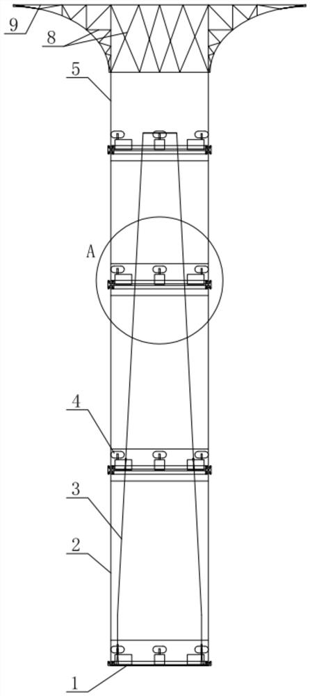
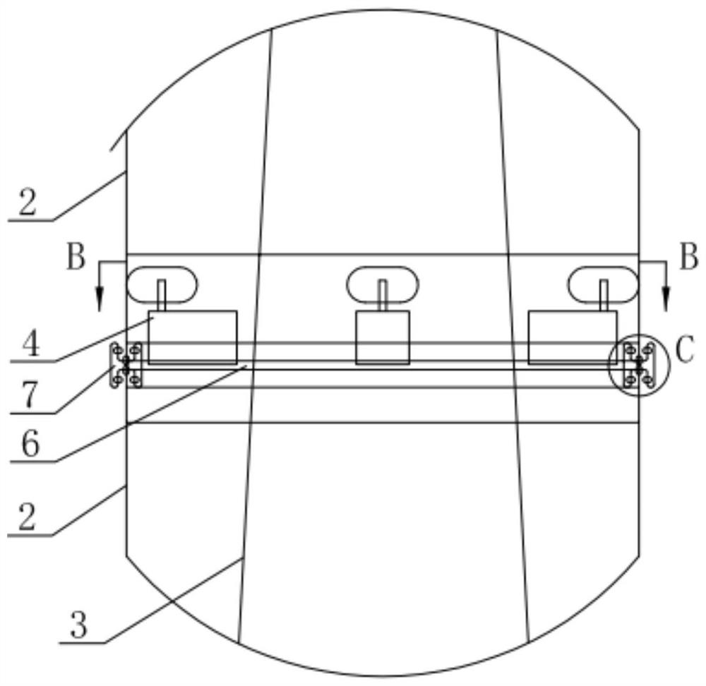
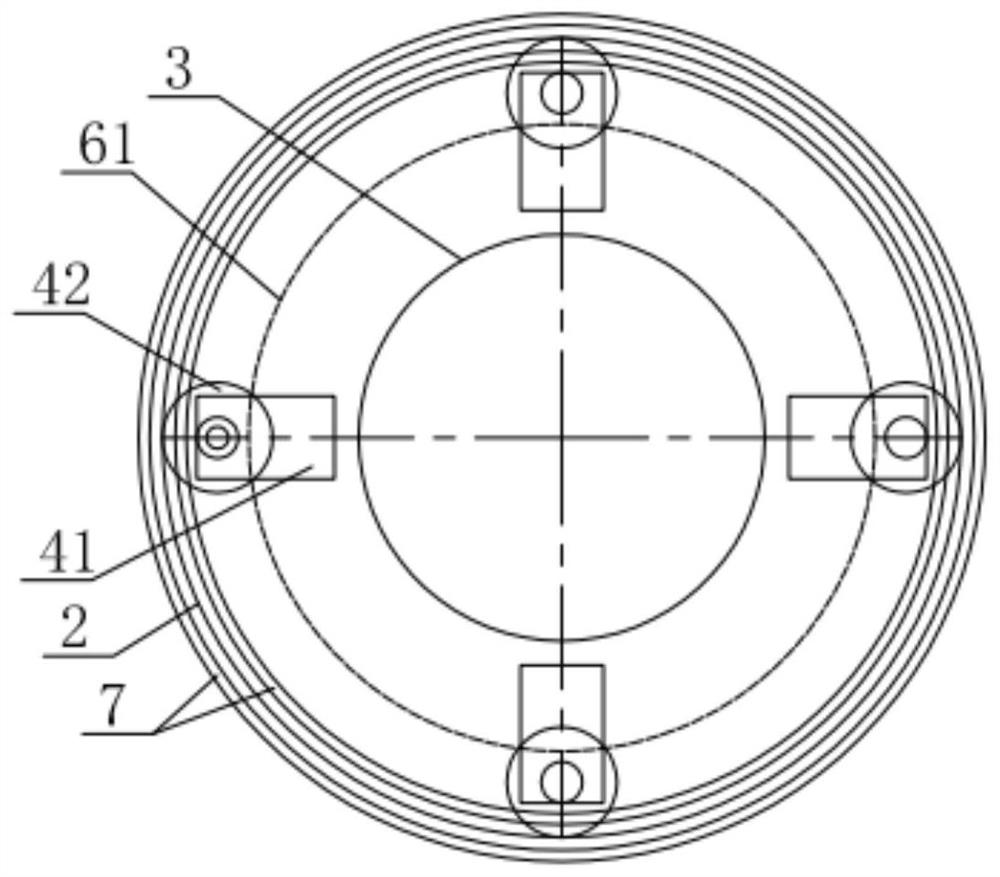
[0031] Such as figure 1 and figure 2 As shown, a wind-assisted rotor structure in this embodiment includes a base 1 on which an inner cylinder 3 is fixedly installed, and a plurality of basic rotors are axially stacked on the base 1 outside the inner cylinder 3. The cylinder 2 and the basic cylinder 2 are concentrically sleeved on the outside of the inner cylinder 3; the inner cylinder 3 between adjacent basic cylinders 2 is provided with partitions 6 to the outside, and the individual basic cylinders 2 are respectively opposite to the partitions in contact with each other. The plate 6 rotates independently; the top of the uppermost basic drum 2 is provided with the same partition 6, and the top drum 5 is rotated above the partition 6; the inner cylinder 3 is accommodated inside the basic drum 2 and the top drum 5; The top of the top dr...


PUM


Abstract

The invention relates to a wind power boosting rotor structure which comprises a base, an inner cylinder is fixedly mounted on the base, a plurality of basic rotating cylinders are axially mounted on the base on the outer side of the inner cylinder in a stacked manner, and the basic rotating cylinders are concentrically arranged outside the inner cylinder in a sleeving manner; partition plates are installed on the outer portion, located between the adjacent basic rotating cylinders, of the inner cylinder in the circumferential direction, and each single basic rotating cylinder independently rotates relative to the partition plate making contact with the basic rotating cylinder. The top of the uppermost basic rotating cylinder is provided with the same partition plate, and a top rotating cylinder is rotationally mounted above the partition plate; the inner cylinder is accommodated in the basic rotating cylinders and the top rotating cylinder; an end plate is arranged at the top end of the top rotating cylinder, and the bottom surface of the end plate is in arc transition connection with the top rotating cylinder body; The rotor is constructed in a modular mode, a large-diameter end plate can be configured, the overall height can be flexibly adjusted, the adaptability is good when wind speeds at different heights change, the lift and resistance generated by the rotor are effectively increased, the rotation torque of the rotor is reduced, and the aerodynamic efficiency of rotor rotation is greatly improved.

Description

technical field [0001] The invention relates to the technical field of ship equipment, in particular to a wind boosting rotor structure. Background technique [0002] Innovative energy-saving technologies such as wind boost have gradually attracted extensive attention from ship owners and ship designers, especially wind boost rotors, which are developing very rapidly. [0003] The working principle of the wind-assisted rotor is the Magnus effect (Magnus effect), that is, the rotating cylinder will be subjected to a lateral force perpendicular to the direction of motion under the action of incoming flow. When a ship equipped with a wind boosting rotor is in a crosswind or oblique wind state, by adjusting the rotation direction of the rotor, the ship can generate thrust in the forward direction, thereby achieving the boosting effect. Compared with wind-assisted technologies such as kites and sails, the wind-assisted rotor has strong adaptability to wind speed and direction, a...

Claims


Application Information

Patent Timeline
IPC IPC(8): B63H9/02
CPCB63H9/02Y02T70/5236
Inventor 胡世良刘希洋胡江平王艳霞孙文愈赵传亮
Owner CHINA SHIP SCIENTIFIC RESEARCH CENTER (THE 702 INSTITUTE OF CHINA SHIPBUILDING INDUSTRY CORPORATION)
Why Eureka
Try Eureka