Device and method for sinking aid of steel pipe pile in hard sandy soil layer using high pressure water jet

A high-pressure water jet, steel pipe pile technology, applied in sheet pile wall, construction, infrastructure engineering and other directions, can solve problems such as use defects, and achieve the effect of improving efficiency, simple operation and strong practicability

Active Publication Date: 2022-07-01
中铁隧道集团一处有限公司 +1
View PDF7 Cites 0 Cited by
  • Summary
  • Abstract
  • Description
  • Claims
  • Application Information

AI Technical Summary

Problems solved by technology

[0008] In view of the above situation, in order to overcome the defects of the prior art, the present invention provides a device and method for aiding the sinking of steel pipe piles in hard sandy soil layers using high-pressure water jets, which effectively solves the defects of the existing water-jet pile sinking method in use. question

Method used


Image

  • Device and method for sinking aid of steel pipe pile in hard sandy soil layer using high pressure water jet
  • Device and method for sinking aid of steel pipe pile in hard sandy soil layer using high pressure water jet
  • Device and method for sinking aid of steel pipe pile in hard sandy soil layer using high pressure water jet

Examples


Embodiment 1

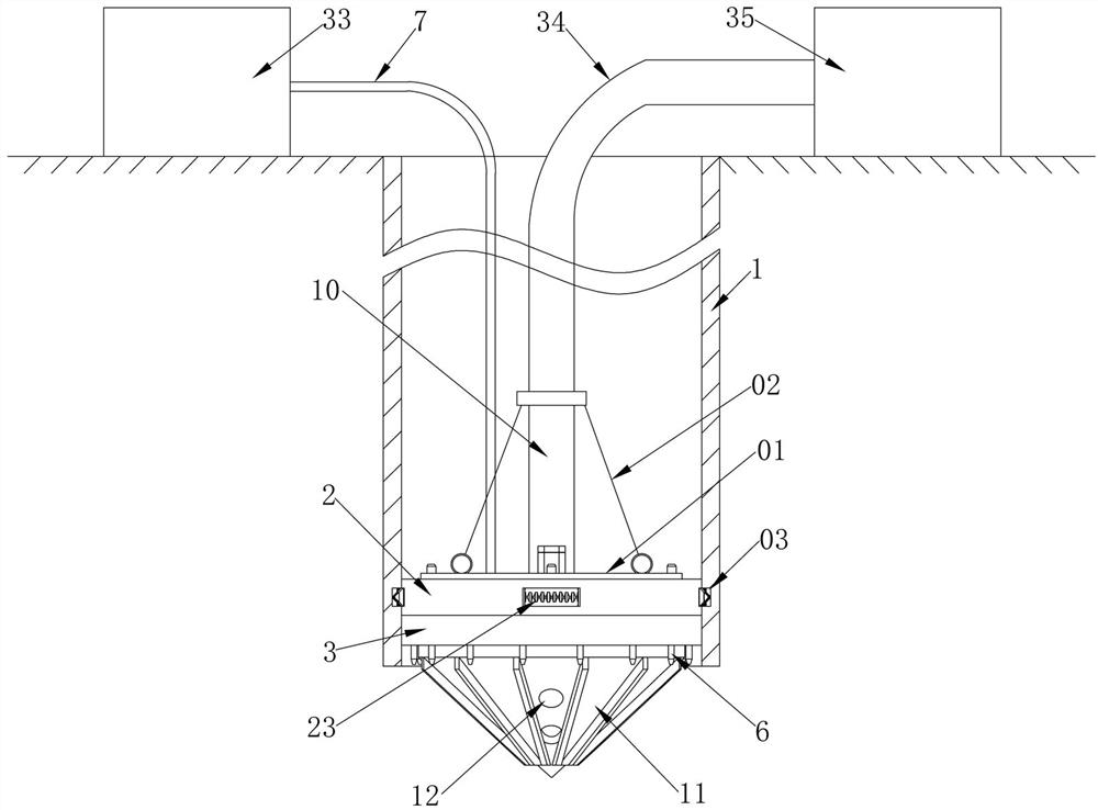
[0033] Embodiment 1, the present invention is a settling aid device for steel pipe piles in hard sandy soil layers using high-pressure water jets, including steel pipe piles 1, and the steel pipe piles 1 are vertically placed in the pre-drilled embedding holes on the ground by a crane, The bottom end inside the steel pipe pile 1 is coaxially and detachably installed with a positioning ring 2 with a top bolt fixed to the top plate 01. The outer diameter of the positioning ring 2 is slightly smaller than the inner diameter of the steel pipe pile 1, so that the positioning ring 2 can be placed in the The steel pipe pile 1 moves up and down coaxially. When installing the positioning ring 2, it can be inserted from one end of the steel pipe pile 1, and then the positioning ring 2 is fixed on the inner wall of the steel pipe pile 1. The top of the top plate 01 is fixedly connected There is a wire rope 02, and the other end of the wire rope 02 is connected with the crane. When the ste...

Embodiment 2

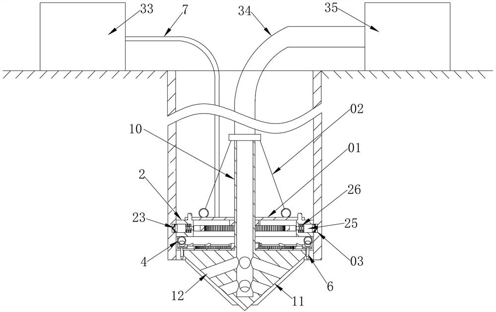
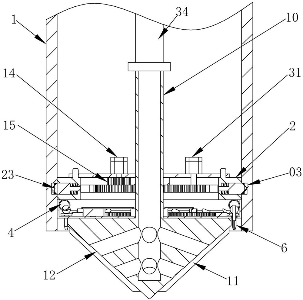
[0036] Embodiment 2, on the basis of Embodiment 1, the water pumping pipe 10 is coaxially fixed with a water pumping pipe gear 13 located below the top plate 01. The water pumping pipe gear 13 can rotate synchronously with the water pumping pipe 10. The top of the 01 is fixedly installed with a pumping pipe motor 14, which is connected to the power supply and control switch on the ground through wires. When the motor 14 rotates, the pumping pipe gear 13 can be driven to rotate through the pumping drive gear 15, thereby driving the sinking drill bit 11 to rotate.

Embodiment 3

[0037] Embodiment 3, on the basis of Embodiment 2, the inner surface of the sprinkler ring 8 is coaxially fixed with a sprinkler ring gear 16, and the sprinkler ring gear 16 can rotate synchronously with the sprinkler ring 8. A sprinkler gear 17 meshing with the sprinkler ring gear 16 is rotatably installed on the bottom surface of the water pump. When the sprinkler gear 17 rotates, it can drive the sprinkler ring gear 16 to rotate. 18. When the water pumping pipe 10 rotates, it can drive the spray head driving ring 18 to rotate synchronously. The spray head driving ring 18 is fixedly connected with the external tooth circular arc rack 19 and the internal tooth circular arc which can be respectively meshed with the spray head gear 17 through the connecting rod 04. rack 20;

[0038] as attached Figure 9 As shown in the figure, if the water pumping pipe 10 is rotated clockwise, the nozzle drive ring 18 can drive the externally toothed circular arc rack 19 and the internal toot...


PUM


Abstract

The invention provides a sinking aid device and method for a steel pipe pile in a hard sandy soil layer by utilizing high-pressure water jets, and solves the problem of defects in the use of the existing water-jet pile sinking method. Including steel pipe piles, a positioning ring is installed inside the steel pipe pile, a positioning annular groove is opened on the inner wall of the bottom end of the steel pipe pile, a positioning device matched with the positioning annular groove is installed on the outer side of the positioning ring, and a water pipe is installed at the bottom of the positioning ring There are annular water pipes installed in the water pipe plate, and a plurality of arc grooves run through the bottom surface of the water pipe plate. The bottom ball of the annular water pipe is hinged with a high-pressure nozzle located in each arc groove, and the annular water pipe is connected to the top plate. For the high-pressure water pipe, a nozzle ring is rotated in the water pipe plate, and nozzle forks located on both sides of each high-pressure nozzle are fixed on the outer surface of the nozzle ring. The steel pipe pile of the present invention can drill the sand layer under the steel pipe pile through the rotating sinking drill bit when the steel pipe pile is piling, so that the obstacles under the steel pipe pile can be cleared, and the pile driving efficiency is improved.

Description

technical field [0001] The invention relates to the technical field of steel pipe pile settling assistance, in particular to a hard sand layer steel pipe pile settling assistance device and method utilizing high-pressure water jets. Background technique [0002] At present, the existing pile driving techniques of steel pipe piles include: hammering pile driving, static pressure pile driving, vibration pile driving, water jet pile driving, etc. For the water jet pipe inside the hollow pile, the high-pressure water flow will loosen the soil layer on the side of the pile or near the tip of the pile, which is convenient for hammering. Generally, the high-pressure water pipe and the high-pressure nozzle are welded on the inner wall of the steel pipe pile, and the high pressure sprayed by the high-pressure nozzle is used. The water flow loosens the sand layer under the steel pipe pile and helps the steel pipe pile to sink. [0003] However, the existing jetting pile driving metho...

Claims


Application Information

Patent Timeline
Patent Type & Authority Patents(China)
IPC IPC(8): E02D5/28E02D7/00E02D7/24E02D5/32
CPCE02D5/28E02D7/00E02D7/24E02D5/32
Inventor 武启诚尹忠辉任昌真张占胜刘常利张浩熊拥军刘天航彭大鸿
Owner 中铁隧道集团一处有限公司
Why Eureka
Try Eureka