Unlock instant, AI-driven research and patent intelligence for your innovation.
Mounting method of fabricated wall
What is Al technical title?
Al technical title is built by PatSnap Al team. It summarizes the technical point description of the patent document.
An installation method and assembly technology, applied in the processing of walls, building materials, construction, etc., can solve the problems of increased labor costs and low installation accuracy, and achieve the effect of improving installation accuracy and high-precision installation
Active Publication Date: 2021-12-21
阳地钢装配式建筑(张家港)有限公司
View PDF8 Cites 0 Cited by
Summary
Abstract
Description
Claims
Application Information
AI Technical Summary
This helps you quickly interpret patents by identifying the three key elements:
Problems solved by technology
Method used
Benefits of technology
Problems solved by technology
In the prior art, in order to accurately install the keel partition wall, at least 2 people are required to cooperate, which increases the labor cost and the installation accuracy is not high
Method used
Image
Click on the blue label to locate the original text in one second.
Reading with bidirectional positioning of images and text.
Examples
Embodiment 1
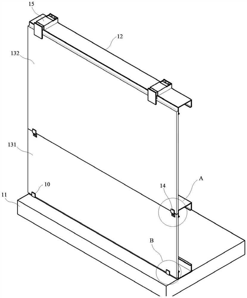
[0038] Embodiment 1: A method for installing a prefabricated wall, the wall includes a base layer 11, a support frame 12 installed on the base layer 11, a lower wall panel 131 and an upper wall panel 132 located outside the support frame 12;
[0039] The installation method includes the following steps:
[0040] Step 1, installing at least two starting supports 10 at the bottom of the supporting frame 12 at intervals;
[0041] Step 2, embed the lower end of the lower wallboard 131 into the starting support 10;
[0042] Step 3, connect the lower wall panel 131 with the crossbeam of the supporting frame 12 through a mounting clip 15;
[0043] Step 4, fixing the lower wall panel 131 with the support frame 12 by nailing;
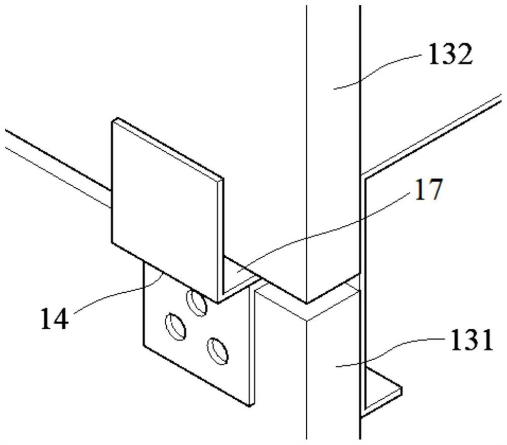
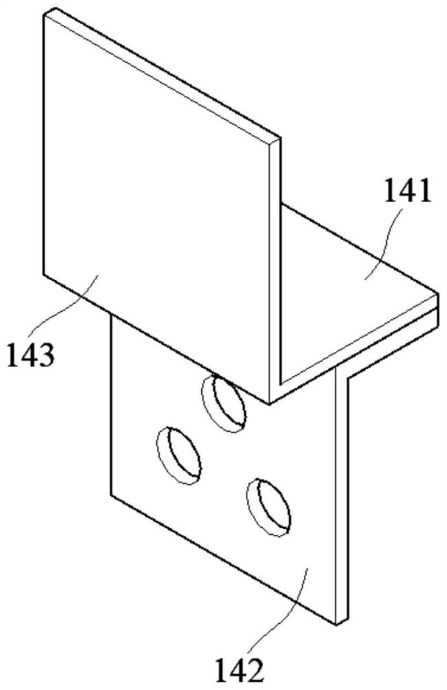
[0044] Step 5, install at least two transitional supports 14 at intervals on the upper part of the lower wall panel 131;
[0045] Step 6, embed the lower end of the upper wallboard 132 into the transition support 14;
[0046] Step 7. Connect the upper wall p...
Embodiment 2
[0053] Embodiment 2: A method for installing a prefabricated wall, the wall includes a base layer 11, a support frame 12 installed on the base layer 11, a lower wall panel 131 and an upper wall panel 132 located outside the support frame 12;
[0054] The installation method includes the following steps:
[0055] Step 1, installing at least two starting supports 10 at the bottom of the supporting frame 12 at intervals;
[0056] Step 2, embed the lower end of the lower wallboard 131 into the starting support 10;
[0057] Step 3, connect the lower wall panel 131 with the crossbeam of the supporting frame 12 through a mounting clip 15;
[0058] Step 4, fixing the lower wall panel 131 with the support frame 12 by nailing;
[0059] Step 5, install at least two transitional supports 14 at intervals on the upper part of the lower wall panel 131;
[0060] Step 6, embed the lower end of the upper wallboard 132 into the transition support 14;
[0061] Step 7. Connect the upper wall p...
PUM
Abstract
The invention discloses a mounting method of a fabricated wall. The mounting method comprises the following steps that firstly, at least two starting supporting pieces are mounted at the bottom of a supporting framework at intervals; secondly, the lower end of a lower wall plate is embedded into a starting supporting piece; thirdly, the lower wall plate is connected with a cross beam of the supporting framework through a mounting clamp; fourthly, the lower wall plate and the supporting framework are fixedly connected through nailing; fifthly, at least two transition supporting pieces are installed on the upper portion of the lower wall plate at intervals; sixthly, the lower end of an upper wall plate is embedded into a transition supporting piece; seventhly, the upper wall plate is connected with the cross beam of the supporting framework through the mounting clamp; and eighthly, the upper wall plate and the supporting framework are fixedly connected through nailing. According to the mounting method of the fabricated wall, through cooperative use of the starting supporting piece, the transition supporting piece and the mounting clamp, efficient and high-precision mounting of the wall plate can be achieved, and mounting work can be completed only through operation of one person.
Description
technical field [0001] The invention relates to the technical field of prefabricated buildings, in particular to a method for installing a prefabricated wall. Background technique [0002] With the rapid development of building construction technology, the construction efficiency of wall panels of house structures is also gradually improving, and the production methods of brick walls have also become various. The method of directly building walls on the construction site is less efficient and accurate. Poor sex has been difficult to keep up with the times. In response to the country's policy guidelines for new buildings that are environmentally friendly, industrialized, rapid, detachable, and material recycling, there is an urgent need to vigorously develop new prefabricated wall technology. [0003] The keel partition wall is a new type of building partition wall, which has the characteristics of light weight, high strength, and strong versatility. It has the functions of ...
Claims
Application Information
Patent Timeline
Application Date:The date an application was filed.
Publication Date:The date a patent or application was officially published.
First Publication Date:The earliest publication date of a patent with the same application number.
Issue Date:Publication date of the patent grant document.
PCT Entry Date:The Entry date of PCT National Phase.
Estimated Expiry Date:The statutory expiry date of a patent right according to the Patent Law, and it is the longest term of protection that the patent right can achieve without the termination of the patent right due to other reasons(Term extension factor has been taken into account ).
Invalid Date:Actual expiry date is based on effective date or publication date of legal transaction data of invalid patent.
