
Long-optical-path gas laser detection absorption cell

A gas laser and absorption cell technology, which is used in measurement devices, material analysis by optical means, instruments, etc., can solve the problems of difficult adjustment of optical path, and achieve increased accuracy, accurate concentration detection, and accurate beam irradiation area. Effect

Pending Publication Date: 2021-12-21
郑州如阳科技有限公司
View PDF0 Cites 4 Cited by
  • Summary
  • Abstract
  • Description
  • Claims
  • Application Information

AI Technical Summary

Problems solved by technology

[0003] The purpose of the present invention is to provide a long optical path gas laser detection absorption cell to solve the problem that the optical path is not easy to adjust

Method used


Image

  • Long-optical-path gas laser detection absorption cell
  • Long-optical-path gas laser detection absorption cell
  • Long-optical-path gas laser detection absorption cell

Examples


Embodiment 1

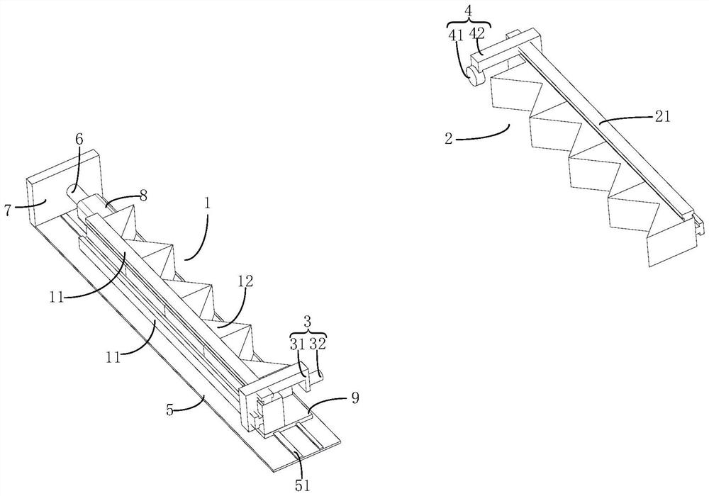
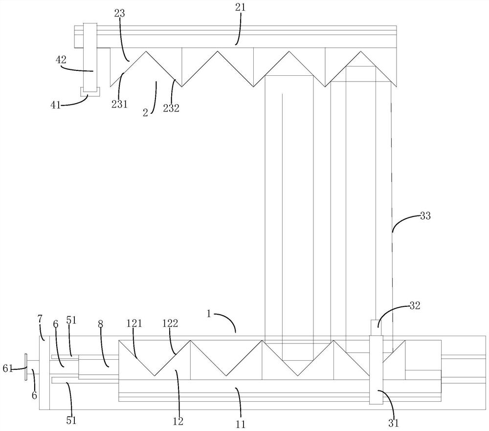
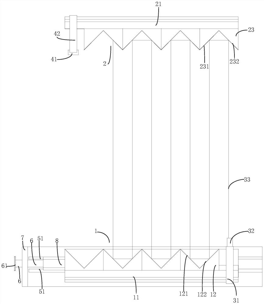
[0027] See attached Figure 1-3 , a long optical path gas laser detection absorption cell, comprising a first prism group 1, a second prism group 2, a laser emitting mechanism 3, a laser receiving mechanism 4 and a moving mechanism; the first prism group 1 and the second prism group 2 Opposite and misplaced, the first prism group 1 and the second prism group 2 are parallel, the laser emitting mechanism 3 can emit the beam 33, the laser receiving mechanism 4 can receive the beam 33, the moving mechanism can move the first prism group 1, and the laser emitting mechanism 3 After the light beam 33 is emitted, the light beam 33 is reflected back and forth between the first prism group 1 and the second prism group 2 , and finally reaches the laser receiving mechanism 4 to receive the light beam 33 .

[0028] The longitudinal direction of the first prism group 1 is parallel to the longitudinal direction of the second reflective surface 122, the longitudinal direction of the first pri...

Embodiment 2

[0039] See attached Figure 4 , also includes a turning prism 22, the turning prism 22 is fixedly connected to the front end of the second prism group 2, the length direction of the turning prism 22 is perpendicular to the length direction of the first prism group 1, and the turning prism 22 includes a fifth reflective surface 221 and the sixth reflective surface 222, the fifth reflective surface 221 and the sixth reflective surface 222 are arranged along the height direction, when a light beam 33 illuminates the fifth reflective surface 221, the fifth reflective surface 221 reflects the light beam 33 to the sixth reflective surface 222 , the sixth reflective surface 222 reflects the light to the first prism group 1 , so as to form two layers of light beams 33 between the first prism group 1 and the second prism group 2 . Other structures are the same as in Example 1, and the method of use is the same as in Example 1.


PUM


Abstract

The invention relates to a long-optical-path gas laser detection absorption cell. The long-optical-path gas laser detection absorption cell comprises a first prism group, a second prism group, a laser emitting mechanism, a laser receiving mechanism and a moving mechanism, wherein the first prism group and the second prism group are oppositely arranged in a staggered mode, the laser emitting mechanism can emit light beams, the laser receiving mechanism can receive the light beams, the moving mechanism can move the first prism group, and after the laser emitting mechanism emits the light beams, the light beams are reflected back and forth between the first prism group and the second prism group; and finally, the light beams are received by the laser receiving mechanism. The first prism group and the second prism group are arranged in the length direction of the first prism group in a staggered mode, the staggered distance between the first prism group and the second prism group can be adjusted through the moving mechanism, the optical path of a light beam can be changed by changing the staggered distance, the changed optical path is large, and therefore concentration detection precision can be improved.

Description

technical field [0001] The invention relates to the field of gas concentration detection, in particular to an absorption cell for long optical path gas laser detection. Background technique [0002] With the growth of population and the development of economy, our country is facing very serious environmental pollution problems. Therefore, the development of analytical instruments that can monitor ambient gases in real time is of great significance to improve the living environment of human beings. However, since most of the polluting gases are low-concentration gases below the ppm level or even the ppb level, the required optical system must have a long enough optical path to meet the detection accuracy requirements. Traditional multiple reflection pools mainly include White pool and Herriott pool. The former is characterized by the use of three concave mirrors with the same curvature radius, and the latter is composed of two concave mirrors. These two reflective pools are...

Claims


Application Information

Patent Timeline
Patent Type & Authority Applications(China)
IPC IPC(8): G01N21/01G01N21/17
CPCG01N21/01G01N21/17G01N21/031
Inventor 柴庆如胡春英韩朝辉徐亚辉韩晓婷杨鹏岑双庆烟殿丕
Owner 郑州如阳科技有限公司
Learn More