Communication engineering-based switch with built-in power supply structure

A switch and engineering technology, applied in the direction of electrical components, selection devices, casings/cabinets/drawer components, etc., can solve the problems of reduced heat dissipation speed of electrical components, interruption of switch transmission information, switch drop, etc., to achieve protection Safety, moisture-proof effect

Inactive Publication Date: 2021-12-21
马良华
View PDF0 Cites 0 Cited by
  • Summary
  • Abstract
  • Description
  • Claims
  • Application Information

AI Technical Summary

Problems solved by technology

[0002] A switch is a device that completes the information exchange function in a communication system. A network switch is a main branch of a switch. The needs of the switch, and the switch is mainly supported by electricity. If there is a sudden power failure, the process of transmitting information by the switch may be interrupted. Therefore, people have developed a switch with a built-in power structure to ensure the integrity of information transmission.
[0003] Existing switches with built-in power supply structures based on communication engineering are mostly equipped with cooling holes, so that the heat inside the switch can be dissipated in time, but when not in use, external dust will enter the switch through the cooling holes In this way, the heat dissipation speed of the electrical components inside the switch is reduced. At the same time, the switch is also equipped with supporting legs. When not in use, the supporting legs increase the storage space of the switch accordingly, and the contact surface between the supporting legs and the table is relatively small. Small, which makes the switch vulnerable to external force and drop

Method used


Image

  • Communication engineering-based switch with built-in power supply structure
  • Communication engineering-based switch with built-in power supply structure
  • Communication engineering-based switch with built-in power supply structure

Examples


Embodiment Construction

[0033] The following will clearly and completely describe the technical solutions in the embodiments of the present invention with reference to the accompanying drawings in the embodiments of the present invention. Obviously, the described embodiments are only some, not all, embodiments of the present invention. Based on the embodiments of the present invention, all other embodiments obtained by persons of ordinary skill in the art without making creative efforts belong to the protection scope of the present invention.

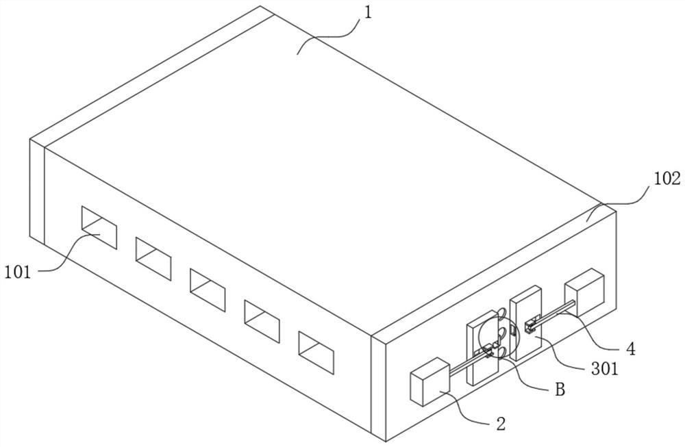
[0034] see Figure 1-9 As shown, the switch based on the built-in power supply structure of communication engineering includes a switch body 1, and a plurality of transfer ports 101 are equidistantly provided on the front of the switch body 1, and the corresponding number of transfer ports 101 can be set according to requirements. External connection lines, both sides of the switch body 1 are fixedly connected with side plates 102, the side plates 102 can effe...


PUM


Abstract

The invention discloses a communication engineering-based switch with a built-in power supply structure. The switch comprises a switch body, a supporting mechanism, a positioning mechanism and an anti-falling mechanism. Side plates are fixedly connected to two sides of the switch body, two movable blocks are rotatably connected to one sides of the two side plates, heat dissipation holes are formed in the middle parts of the two side plates, and the heat dissipation holes are formed in the middle parts of the two movable blocks; the supporting mechanism is arranged on one side of the side plate and comprises a left supporting plate, a right supporting plate, a sliding groove, a connecting rod and a sliding block, the positioning mechanism is arranged in the sliding block, and the anti-falling mechanism is arranged at the joint of the left supporting plate and the right supporting plate. The beneficial effects of the invention are that through the design of the left supporting plate and the right supporting plate, when the switch body is used, the left supporting plate and the right supporting plate play a role of supporting legs, and when the switch body is not used, the left supporting plate and the right supporting plate can be spliced at the outer sides of the heat dissipation holes; therefore, external dust can be prevented from entering the switch body.

Description

technical field [0001] The invention relates to a switch, in particular to a switch with a built-in power supply structure based on communication engineering, and belongs to the technical field of network switches. Background technique [0002] A switch is a device that completes the information exchange function in a communication system. A network switch is a main branch of a switch. In order to meet the needs of the switch, the switch mainly uses electricity to support the operation. If there is a sudden power failure, the process of transmitting information by the switch may be interrupted. Therefore, people have developed a switch with a built-in power structure to ensure the integrity of information transmission. [0003] Existing switches with built-in power supply structures based on communication engineering are mostly equipped with cooling holes, so that the heat inside the switch can be dissipated in time, but when not in use, external dust will enter the switch t...

Claims


Application Information

Patent Timeline
Patent Type & Authority Applications(China)
IPC IPC(8): H04Q1/04H04Q1/02H05K5/02
CPCH04Q1/04H04Q1/035H05K5/0204H05K5/0213H05K5/03
Inventor 马良华
Owner 马良华
Why Eureka
Try Eureka