
Controlled detachment features of steering column mounted camera

A technology of mounting structure and characteristic structure, applied in the field of camera components

Pending Publication Date: 2021-12-21
维宁尔美国有限责任公司
View PDF0 Cites 0 Cited by
  • Summary
  • Abstract
  • Description
  • Claims
  • Application Information

AI Technical Summary

Problems solved by technology

In addition, it is desirable to protect the sensitive and expensive display components from mechanical damage caused by impact or any other condition in which the camera may move from its mounted position in front of the display

Method used


Image

  • Controlled detachment features of steering column mounted camera
  • Controlled detachment features of steering column mounted camera
  • Controlled detachment features of steering column mounted camera

Examples


Embodiment Construction

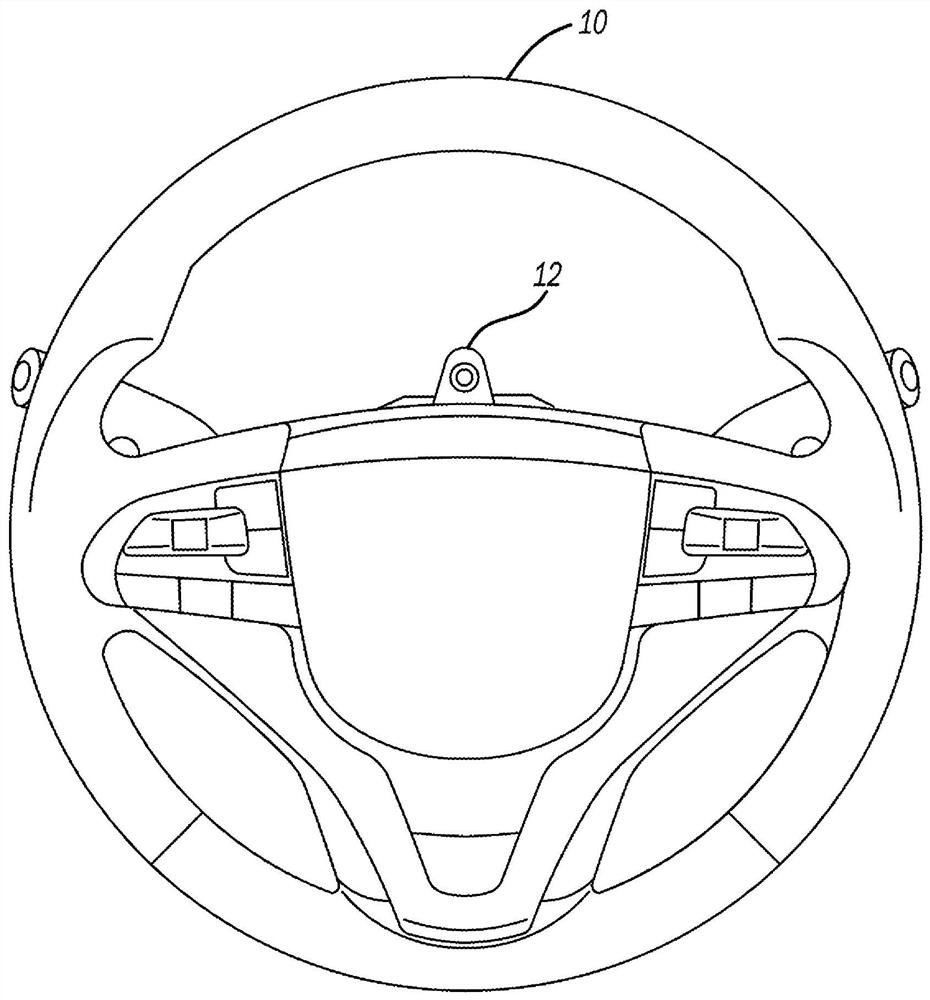
[0014] figure 1 An example of a motor vehicle steering wheel assembly 10 is shown from the perspective of a driver's position behind the steering wheel. A small portion of camera assembly 12 can be seen in the upper open quadrant of steering wheel assembly 10 .

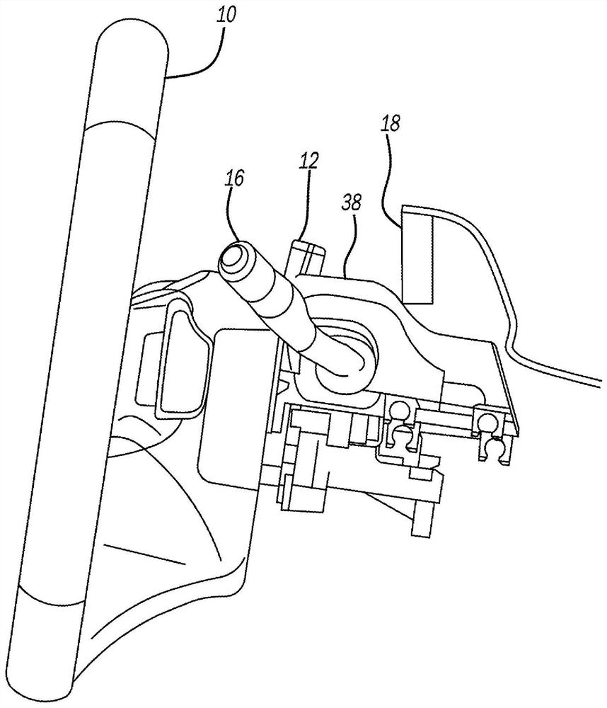
[0015] figure 2 is a side view of the steering wheel assembly 10 showing the location of the steering column 14 and control handle 16 and the display 18, which is typically integrated into the dashboard of the vehicle. As shown, there is a close spacing in the fore-aft (vehicle forward travel) direction between the camera assembly 12 and the display 18 . For reasons previously discussed, it is desirable to protect the display 18 from damage and to otherwise control the movement of the camera assembly 18 when it is removed from its mounting position during an impact or other event.

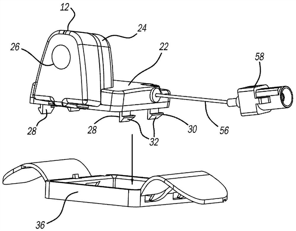
[0016] image 3 A pictorial view of camera assembly 12 is provided. As shown, the camera assembly 12 includes a generally planar ho...


PUM


Abstract

A camera assembly adapted for mounting to an interior of a motor vehicle on an upper surface of the steering column assembly is disclosed. The camera assembly has mounting features interacting with a mounting structure that cause the camera assembly to separate from the mounting structure upon the occurrence of a collision with an object or through inertial forces acting on the camera assembly. The separation in such conditions is provided in a controlled manner through the use of cam or ramp surfaces provided in the camera assembly or mounting structure. A cable or tether may be attached to the camera assembly and mounted to the vehicle to further control movement of the camera assembly after separation.

Description

[0001] Cross References to Related Applications [0002] This PCT application claims the benefit of priority under 35 U.S.C. §1 19 to U.S. Provisional Patent Application No. 62,852,737, filed May 24, 2019, the entire contents of which are incorporated herein by reference. technical field [0003] The present application generally relates to camera assemblies for installation in the interior of a motor vehicle. Background technique [0004] The motor vehicle of the present invention incorporates features for controlling vehicle functions and providing a comfortable environment for the vehicle occupants, while providing access to information, media and communication functions. Another main purpose is to provide occupant protection. Occupant protection methods can be divided into two main areas; active safety and passive safety. Passive safety features include inflatable restraints, seat belts and other features that deploy in the event of a vehicle impact or rollover. Activ...

Claims


Application Information

Patent Timeline
IPC IPC(8): B60R11/04G03B17/56
CPCB60R11/04B60R2011/001G03B17/561G03B30/00B60K35/00B60R2011/0059B60R2011/0071H04N23/54H04N23/57B60K35/22B60K2360/691
Inventor 查克拉瓦蒂·马利卡君·纳古鲁弗朗西斯·约瑟夫·贾琦
Owner 维宁尔美国有限责任公司
Learn More