Pluggable quick-release type anti-reflux self-locking plectrum refill
An anti-backflow, self-locking technology, applied in the direction of pen tip, ballpoint pen, printing, etc., can solve the problems of cumbersome pen manufacturing, ink flowing out, ink discarding, etc.
- Summary
- Abstract
- Description
- Claims
- Application Information
AI Technical Summary
Problems solved by technology
Method used
Image
Examples
Embodiment 1
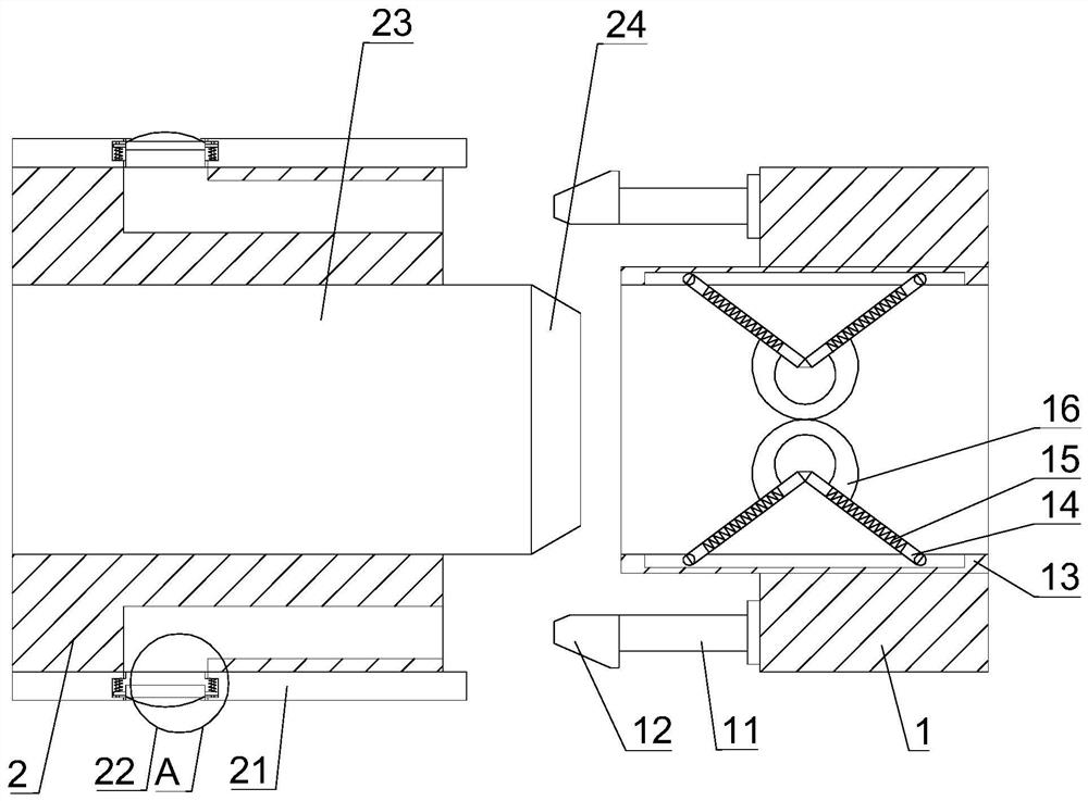
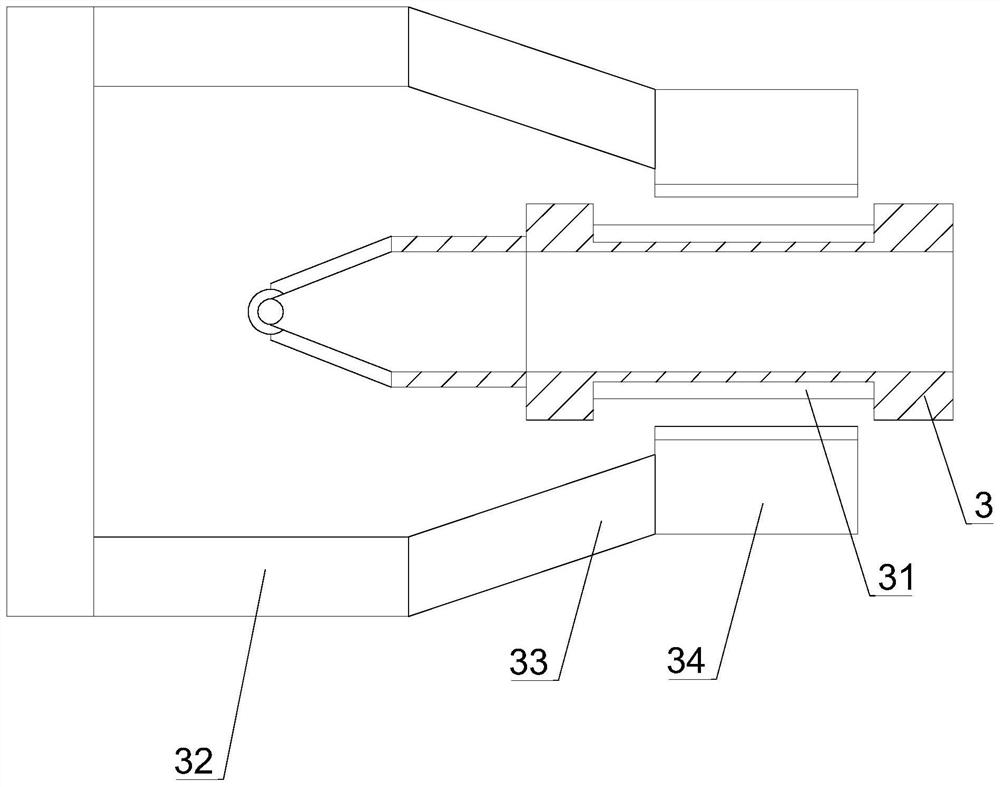
[0032] Such as Figure 1-5 As shown, the present invention provides a plug-and-pull quick-release anti-backflow self-locking paddle refill, which includes a refill 1, a clamp joint 2 and a nib 3, and the top of the pen core 1 is movably clamped with a clamp joint 2 , A nib 3 is provided on the top of the clip connector 1 2 .
[0033] In this embodiment, one end of the card joint 2 and the pen core 1 is clamped, and when the pen head is replaced, the card joint one 2 is pulled out from a point of the pen core 1 through the surface of the pen head 3, and the pen core is used. 1 Seal the ink inside.
[0034] Such as Figure 1-5 As shown, in this embodiment, preferably, the outer surface of the friction plate 31 is provided with a protrusion 311, and the outer surface of the friction plate 31 is provided with a groove 312, and the protrusion 311 on one end of the tweezers and the nib 3 The groove 312 on the surface is docked to increase the internal friction.
Embodiment 2
[0036] Such as Figure 1-5 As shown, on the basis of embodiment 1, the present invention provides a kind of technical scheme: preferably, the upper and lower outer surfaces of the nib 3 are provided with a square hollow groove, and the outer surface of the nib 3 is movably overlapped with tweezers 32, and the tweezers 32 One end on the right side is provided with an elastic force extruding arm 33, and one end of the elastic force extruding arm 33 is provided with a snap joint two 34, and a friction plate 31 is provided on the snap joint two 34 and the outer surface of one side of the square cavity.
[0037] In this embodiment, by attaching the clamp joint 2 34 on one end of the tweezers 32 to the surface of the nib, the clamp joint 2 34 is clamped to the square empty groove on the surface of the nib 3, and the friction plate 31 is used for lamination. , extruding, pulling the tweezers 32 to quickly pull out the nib 3 from one end of the pen core 1, so as to achieve the effect ...
Embodiment 3
[0039] Such as Figure 1-5 Shown, on the basis of embodiment 1, the present invention provides a kind of technical scheme: preferably, the upper and lower outer surfaces of the left side of the pen core 1 are fixedly connected with a micro-elastic rod 11, and one end of the micro-elastic rod 11 is fixedly connected with a Multi-sided card joint 12, the inner surface of the pen core 1 is fitted with a built-in card connection plate 13, and the upper and lower inner surfaces of the built-in card connection plate 13 are fixedly connected with an elastic butt joint plate 14, and the outer surface of the elastic butt joint plate 14 is An elastic sheet 15 is provided, an elastic extrusion soft ring 16 is fixedly connected to one end of the elastic docking plate 14, and an external protective plate 21 is attached to the upper and lower outer surfaces of the snap joint-2, and the outer right side of the snap joint-2 There is an L-shaped hollow groove on the surface, one end of the L-s...
PUM
 Abstract
Description
Claims
Application Information
 - R&D
- Intellectual Property
- Life Sciences
- Materials
- Tech Scout
- Unparalleled Data Quality
- Higher Quality Content
- 60% Fewer Hallucinations
Browse by: Latest US Patents, China's latest patents, Technical Efficacy Thesaurus, Application Domain, Technology Topic, Popular Technical Reports.
© 2025 PatSnap. All rights reserved.Legal|Privacy policy|Modern Slavery Act Transparency Statement|Sitemap|About US| Contact US: help@patsnap.com


