Supercharge Your Innovation With Domain-Expert AI Agents!

Sewage treatment equipment based on rotary uniform stirring of water treatment agent

A sewage treatment equipment and water treatment agent technology, applied in water/sewage treatment equipment, water/sewage treatment, water/sludge/sewage treatment, etc., can solve problems such as reduced service life, filter corrosion, and single filter structure , to achieve the effect of increasing the service life and improving the cleanliness

Active Publication Date: 2021-12-24
安徽棣泽环保科技有限公司
View PDF4 Cites 0 Cited by
  • Summary
  • Abstract
  • Description
  • Claims
  • Application Information

AI Technical Summary

Problems solved by technology

[0003] Among them, the current sewage treatment equipment is divided into large and small. For small domestic sewage treatment equipment, the sewage is firstly filtered through a large amount of impurities contained in the interior, and then flows down into the warehouse of the treatment equipment, and the water treatment agent is added. Then mix and stir to achieve the uniform mixing and dissolving of the water treatment agent, and then the sewage can be treated and purified. However, the current preliminary filtration structure is single, and only the filter screen is installed for filtering operations, and the installation of the filter screen is mostly fixed. At the same time, the current sewage treatment does not have an auxiliary structure that can clean or replace the filter screen after long-term use. Furthermore, the filter screen is easily corroded by impurities in the sewage after use, so that the existing sewage treatment The equipment can not achieve good use effect, and the service life is reduced

Method used


Image

  • Sewage treatment equipment based on rotary uniform stirring of water treatment agent
  • Sewage treatment equipment based on rotary uniform stirring of water treatment agent
  • Sewage treatment equipment based on rotary uniform stirring of water treatment agent

Examples


Embodiment 1

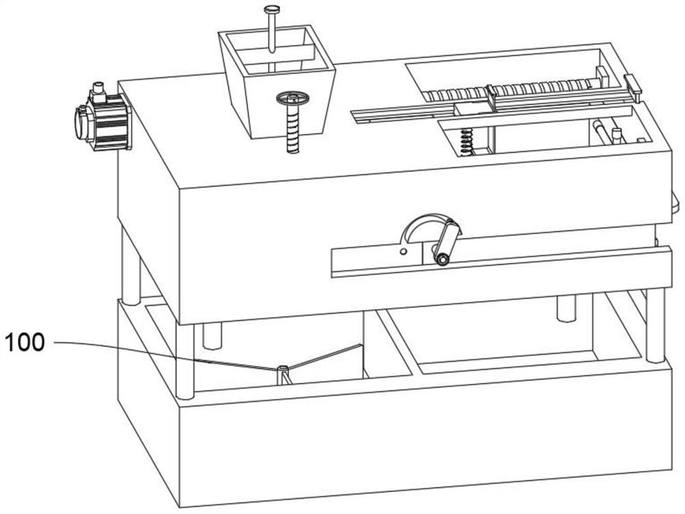
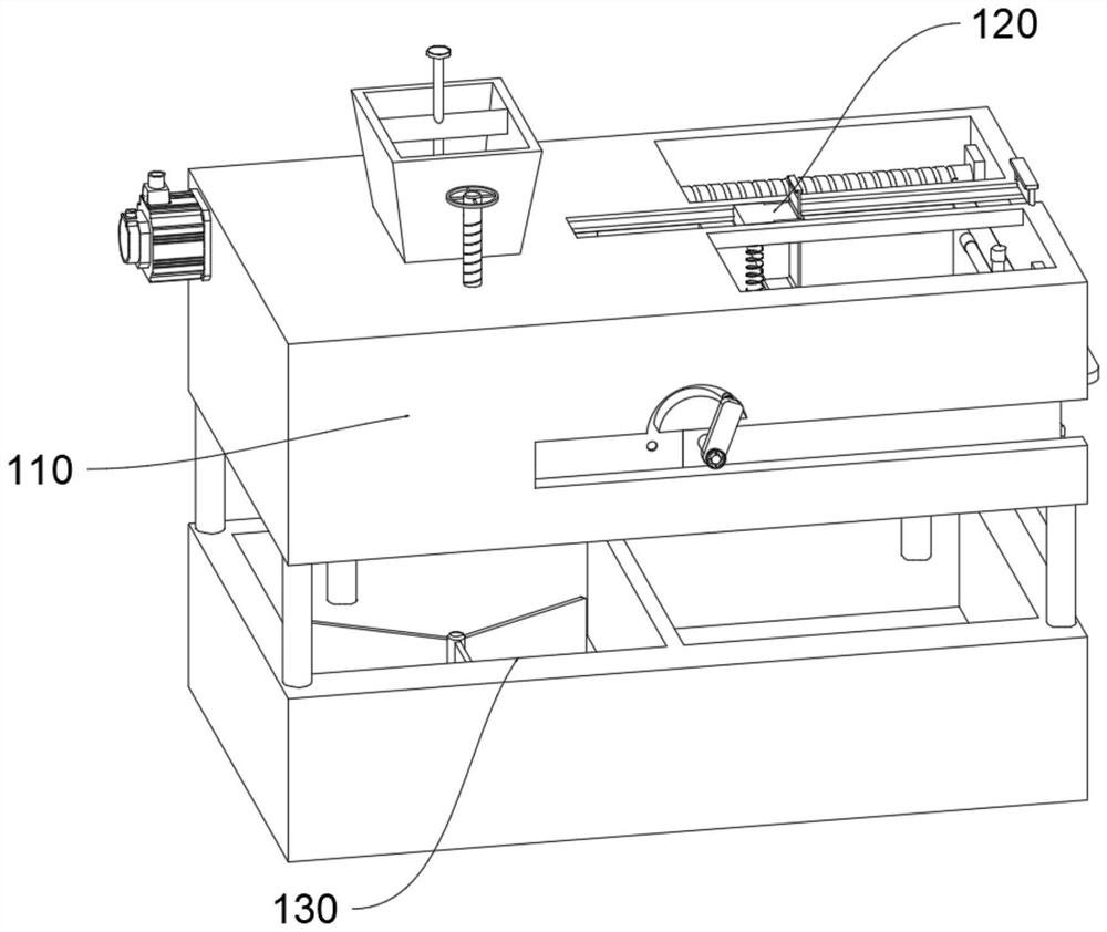
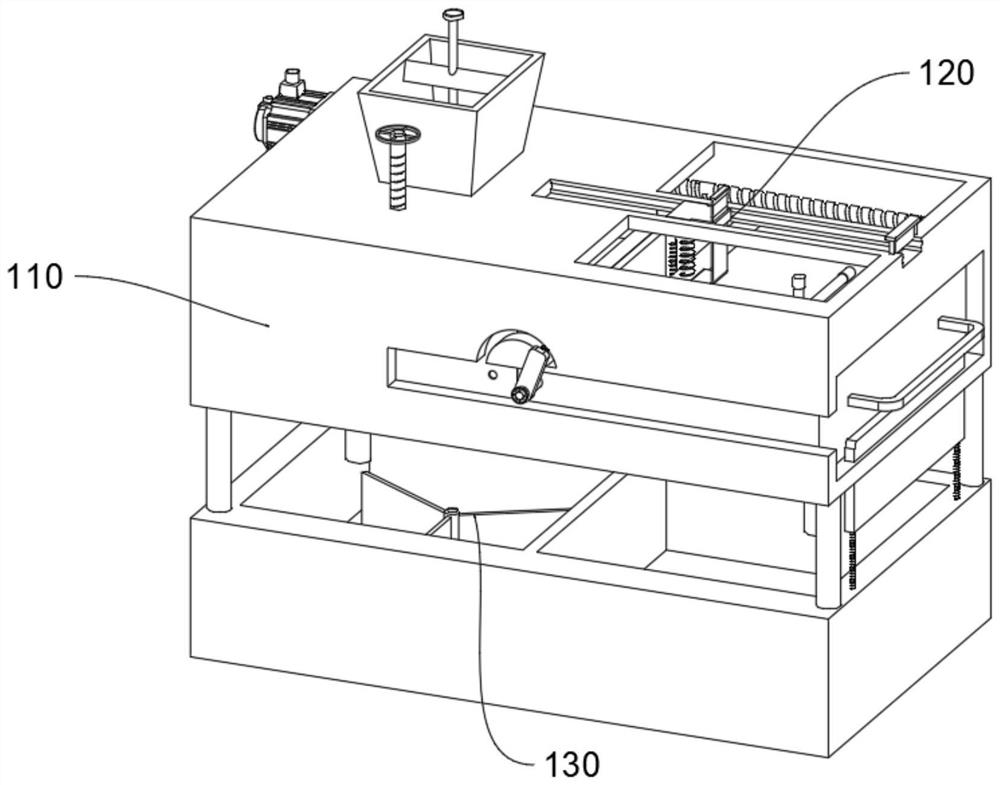
[0044] see Figure 1-Figure 9 As shown, the purpose of this embodiment is to provide a sewage treatment equipment based on a rotating water treatment agent uniformly stirred, including a sewage treatment device 100, and the sewage treatment device 100 at least includes:

[0045] Filter body 110, filter body 110 comprises casing 111, and the upper surface of casing 111 is communicated with liquid inlet bin 112, and the inside of casing 111 is provided with filter bin 113, and the inside of filter bin 113 is connected with filter plate 1134, the inner wall upper side of casing 111 A driving assembly 114 is provided, and the driving assembly 114 includes a driving screw 1141 and a cross bar 1146. The surfaces of the driving screw 1141 and the cross bar 1146 are connected with guide rods 1142, and the bottoms of the guide rods 1142 are provided with guide springs 1143 , the bottom of the guide spring 1143 is equipped with a magnetic plate 1144, one end of the filter chamber 113 is...

Embodiment 2

[0056] In order to facilitate simultaneous removal of the filter chamber 113 and the cleaning chamber 115, the difference between this embodiment and Embodiment 1 is that please refer to Figure 7 with Figure 10 Shown:

[0057]Wherein, the side wall of the housing 111 is provided with an arc opening 1112, one end of the surface of the filter chamber 113 is provided with a fixing hole 1133, and the side wall of the cleaning chamber 115 is equipped with a connection assembly 117, the connection assembly 117 includes a connection shaft 1171, and the connection shaft 1171 runs through the casing 111 communicates with the cleaning chamber 115, the surface of the connecting shaft 1171 is rotatably connected with a fixed plate 1172, and one end of the surface of the fixed plate 1172 is equipped with a connecting buckle 1174 through a connecting spring 1173, and the connecting spring 1173 can slide along the inside of the arc mouth 1112, and the connecting buckle 1174 is connected a...

Embodiment 3

[0059] In order to improve the practical effect of the end chamber 1114, the difference between this embodiment and Embodiment 1 is that, please refer to Figure 11 Shown:

[0060] Wherein, the inner side of the end chamber 1114 is provided with an upper plate 122, the side ends of the upper plate 122 are provided with side rods 1221, the side rods 1221 are plugged and fixed with the housing 111, and a baffle plate 1222 is installed between the side rods 1221, wherein The baffle plate 1222 can block the inside of the end cavity 1114, that is, close the end cavity 1114, prevent the cleaning slider 121 from sliding out of the end cavity 1114, and at the same time, when the cleaning slider 121 needs to be moved out of the cleaning plate 1212, it can be moved upward. Pull out the upper plate 122 , that is, the side bar 1221 and its baffle 1222 leave the interior of the end chamber 1114 , and the cleaning slider 121 can slide out along the end chamber 1114 .


PUM


Abstract

The invention relates to the technical field of sewage treatment, and concretely relates to sewage treatment equipment based on rotary uniform stirring of a water treatment agent. The equipment comprises a sewage treatment device. The sewage treatment device at least comprises: a filter body, wherein the filter body comprises a shell, a liquid inlet bin, a filter bin and a filter plate, a driving assembly is arranged on the upper side of the inner wall of the shell and comprises a driving lead screw, a cross rod, a guide rod, a guide spring, a magnetic plate and a cleaning bin, a screw rod is arranged on the surface of the shell, and the bottom of the screw rod can make contact with the magnetic plate; and a cleaning body comprising a cleaning sliding block, wherein a top cavity is formed in one side of the surface of the shell, a transverse plate is arranged in the top cavity, an end cavity is formed in the surface of the transverse plate, the lower portion of the cleaning sliding block is connected with a cleaning plate through a cleaning spring, and a sliding plate is inserted into one end of the cleaning sliding block. The filter plate can be adaptively moved into the cleaning bin to be cleaned, so that the used filter plate is timely cleaned every time, and the service life of the filter plate and the sewage treatment equipment is prolonged.

Description

technical field [0001] The invention relates to the technical field of sewage treatment, in particular to sewage treatment equipment based on the uniform stirring of a rotating water treatment agent. Background technique [0002] Sewage treatment is the process of purifying sewage to meet the water quality requirements for discharge into a certain water body or for reuse. Sewage treatment is widely used in various fields such as construction, agriculture, transportation, energy, petrochemical, environmental protection, urban landscape, medical treatment, catering, etc., and it is also increasingly entering the daily life of ordinary people. [0003] Among them, the current sewage treatment equipment is divided into large and small. For small domestic sewage treatment equipment, the sewage is firstly filtered through a large amount of impurities contained in the interior, and then flows down into the warehouse of the treatment equipment, and the water treatment agent is added...

Claims


Application Information

Patent Timeline
Patent Type & Authority Applications(China)
IPC IPC(8): C02F9/02B01D29/03B01D29/64B01D29/96
CPCC02F1/001B01D29/03B01D29/6484B01D29/96C02F2201/002C02F2201/004C02F2201/005C02F2303/02C02F2303/14C02F2303/16Y02W10/10
Inventor 李治俊王雅钟月月孙建军
Owner 安徽棣泽环保科技有限公司
Features
  • R&D
  • Intellectual Property
  • Life Sciences
  • Materials
  • Tech Scout
  • Unparalleled Data Quality
  • Higher Quality Content
  • 60% Fewer Hallucinations
Learn More