Ecological evaporation overflow pool

An overflow pool and ecological technology, applied in water/sludge/sewage treatment, sea area engineering, sewage discharge, etc., can solve the problems of easy collapse of mortar stone pool walls, poor rainwater pressure energy dissipation, and construction difficulties of concrete pool walls To achieve the effect of increasing the area of ​​seepage channels, improving the energy dissipation effect, and strengthening the coordination effect of the landscape

Pending Publication Date: 2021-12-24
SHANXI CONSTR ENG CO LTD
View PDF0 Cites 0 Cited by
  • Summary
  • Abstract
  • Description
  • Claims
  • Application Information

AI Technical Summary

Problems solved by technology

[0002] In the construction of highways in mountainous areas, in order to save land resources, the line type is generally planned according to the mountains, especially in the terrain where the upstream is a valley and the downstream is an open land. It is difficult to drain water. To solve the above problems, the existing technology generally adopts an evaporation pool structure for water collection. Relying on evaporation to drain water, this type of evaporation pool is mostly a regular rectangle, and the walls of the pool are mostly rubble or concrete, and the bottom of the pool is mostly dry rubble. There are some disadvantages in this type of evaporation pool, 1. The energy dissipation of rainwater pressure The effect is poor, and it has a limited effect on reducing the erosion of the land downstream of the pond; 2. The seepage structure of the dry rubble depends entirely on the seepage between the cracks, the seepage channel is narrow, and the seepage time is long. Evaporative drainage takes a long time, and the drainage effect is basically not achieved in the rainy season; 3. The pool is easy to silt in the rainy season, and the frequency of manual dredging is high; Difficult construction on steep slopes

Method used


Image

  • Ecological evaporation overflow pool
  • Ecological evaporation overflow pool
  • Ecological evaporation overflow pool

Examples


Embodiment Construction

[0026] In order to further illustrate the technical solution of the present invention, the present invention will be further described below through examples.

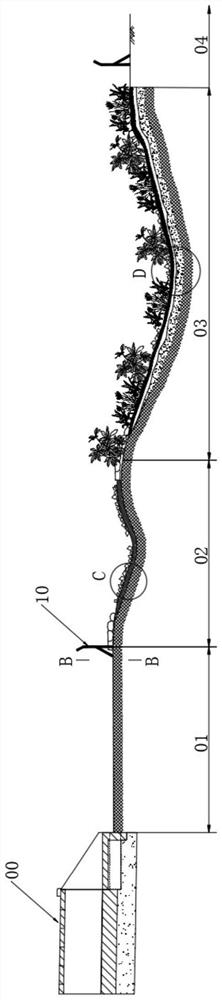
[0027] An ecological evaporation overflow pool, including a drainage section 01, an energy dissipation section 02, a water storage seepage section 03 and an overflow section 04 connected in sequence, and the drainage section 01, the energy dissipation section 02, and the water storage seepage section 03 from Arranged from high to low, the height of the overflow section 04 is not higher than the highest point of the water storage seepage section 03. The drainage section 01 shown is used to drain the rainwater discharged from the culvert; the energy dissipation section 02 is used to relieve the pressure of the rainwater; the water storage seepage section 03 is used to store the rainwater discharged from the culvert, and make the rainwater Evaporation and water seepage are carried out in the water seepage section 03; the ...


PUM

PropertyMeasurementUnit
Thicknessaaaaaaaaaa
Thicknessaaaaaaaaaa
Densityaaaaaaaaaa

Abstract

The invention belongs to the technical field of water treatment, and particularly relates to an ecological evaporation overflow pool which comprises a drainage section, an energy dissipation section, a water storage and seepage section and an overflow section which are connected in sequence, the drainage section, the energy dissipation section and the water storage and seepage section are arranged in sequence from high to low, and the overflow section is not higher than the highest point of the water storage and seepage section. The drainage section, the energy dissipation section, the water storage and seepage section, the overflow section and other functional zones are divided, the energy dissipation effect on rainwater pressure is greatly improved, rainwater drainage is accelerated through the evaporation effect, the seepage effect and the water retention effect of vegetation in the water storage and seepage section, the deposition amount is greatly reduced, and a large amount of dredging and maintenance labor cost is saved; meanwhile, by means of ecological greening in the water storage and seepage section, the proposed highway and the surrounding landscape are integrated, and the strong landscape coordination effect is achieved.

Description

technical field [0001] The invention belongs to the technical field of water treatment, and in particular relates to an ecological evaporation overflow pool. Background technique [0002] In the construction of highways in mountainous areas, in order to save land resources, the line type is generally planned according to the mountains, especially in the terrain where the upstream is a valley and the downstream is an open land. It is difficult to drain water. To solve the above problems, the existing technology generally adopts an evaporation pool structure for water collection. Relying on evaporation to drain water, this type of evaporation pool is mostly a regular rectangle, and the walls of the pool are mostly rubble or concrete, and the bottom of the pool is mostly dry rubble. There are some disadvantages in this type of evaporation pool, 1. The energy dissipation of rainwater pressure The effect is poor, and it has a limited effect on reducing the erosion of the land dow...

Claims


Application Information

Patent Timeline
IPC IPC(8): E03F3/04E03F5/10E03F5/14E03F1/00E02B7/16E02B8/06
CPCE03F3/046E03F5/10E03F5/14E03F1/00E03F1/002E02B7/16E02B8/06
Inventor 孙兆刚邓将赵川沙克非闫龙柴晓杰郭瑞娇李治秦晋武郭冬勇
Owner SHANXI CONSTR ENG CO LTD
Why Eureka
Try Eureka