Special-shaped streaming trickle irrigation device

A sprinkler and special-shaped technology, which is applied in watering devices, horticulture, botanical equipment and methods, etc., can solve the problems of serialization degree to be improved, fewer product varieties and specifications, and deposition of impurities in water, etc., to achieve good outflow stability and anti-clogging ability, large average section size, and strong water flow turbulence

Inactive Publication Date: 2012-07-18
JIANGSU UNIV
View PDF9 Cites 6 Cited by
  • Summary
  • Abstract
  • Description
  • Claims
  • Application Information

AI Technical Summary

Problems solved by technology

[0003] Since the introduction of drip irrigation technology in China in 1974, drip irrigation emitters have experienced orifice type, eddy current type, micro-tube, threaded long channel type, double-cavity tube micro-irrigation tape, labyrinth channel type and various forms of pressure-compensated emitters. During the development process, we developed the flank labyrinth drip irrigation belt, the inner panel labyrinth drip irrigation tube (belt), the inner column labyrinth drip irrigation tube, the inner strip drip irrigation belt, the pressure compensation drip irrigation tube, and the inter-pipe drip irrigation tube. , drip arrow drippers, underground drip irrigation pipes and other products, the products are becoming more and more abundant, and the technical level is constantly improving; but compared with foreign developed countries, domestic product varieties and specifications are relatively small, and the degree of serialization needs to be improved. Product design capabilities, research and development cycles, There is still a certain gap in the manufacturing process and performance indicators; the current development trend of low pressure, low energy consumption, and low cost of the drip irrigation system makes the drip irrigation system put forward higher requirements for the structure, performance and manufacturing level of the drip irrigation emitter. A good drip irrigation emitter can reduce the flow index, improve the stability of the emitter outflow, enhance the anti-clogging ability of the flow channel, reduce the working pressure and cost of the emitter, reduce the energy consumption and engineering investment of the drip irrigation system, and promote the diversification of drip irrigation emitter products development and application
[0004] Application No. 200620134352.7 of the Chinese patent "Micro-peristaltic variable-diameter labyrinth drip irrigation belt" embodiment 5 and the Chinese patent No. 200910023158.X "a water-saving irrigation device with internal teeth to tooth-shaped flow channels" disclose a The plane projection of the flow channel unit is trapezoidal, and the drip irrigation emitter flow channel with the inlet and outlet of the flow channel unit on the two bottom sides of the trapezoid. The two sides of the long bottom side of the trapezoid are sharp corners, and there is no built-in surrounding fluid; The Chinese patent "Triangle Circular Drip Irrigation Emitter Flow Channel" discloses a drip irrigation emitter flow channel in which the plane projection of the flow channel unit is trapezoidal. The sides are sharp corners, with built-in regular triangular surrounding fluid in the same direction, and the facing surface is a plane, which only has the effect of circumventing the flow, and has no reverse deflection effect. The sharp corners on both sides are prone to form low-speed stagnation zones, which may easily lead to the deposition and condensation of impurities in the water. Block and block the emitter; the Chinese patent "triangular bypass drip irrigation emitter flow channel" with the application number of 200810236179.5 discloses a flow channel unit whose plane projection is trapezoidal, and there are flow channel unit inlets and outlets on the two bottom edges of the trapezoid The flow channel of the drip irrigation emitter has sharp corners on the two sides of the long bottom of the trapezoid, and a regular triangular surrounding fluid is built in the reverse direction. It is easy to form a low-speed stagnation zone, which can easily lead to the deposition of impurities in the water, agglomeration, and blockage of the emitter; the Chinese patent "Scaling Cylindrical Circumferential Drip Irrigation Emitter Flow Channel" with application number 200810123829.5 discloses a flow channel unit plane The projection is trapezoidal. There are flow channel unit inlet and outlet outlets on the two bases of the trapezoid. The two sides of the trapezoidal long base are sharp corners. The effect of circumventing the flow, without the effect of reverse deflecting flow, is easy to form a low-speed stagnation zone in the sharp corners on both sides, which may easily lead to the deposition of impurities in the water, agglomeration, and blockage of the emitter; the Chinese patent application number 200410061282.2 "a piece winding "Flow Sprinkler" discloses a drip irrigation emitter whose planar projection of the flow channel unit is rhombus, and the two top corners of the rhombus have the inlet and outlet of the flow channel unit. The built-in rhombus surrounds the fluid. No reverse deflection effect

Method used


Image

  • Special-shaped streaming trickle irrigation device
  • Special-shaped streaming trickle irrigation device
  • Special-shaped streaming trickle irrigation device

Examples


Embodiment 1

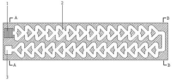
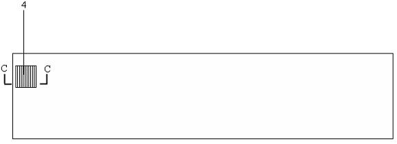
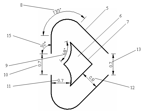
[0025] refer to figure 1 , figure 2 , image 3 , Figure 4 , Figure 5 and Figure 6 , the special-shaped bypass drip irrigation emitter is composed of water inlet tank 1, flow channel, water outlet tank 3, and filter window 4. The filter window 4 is set at the bottom of the water inlet tank 1, and the water inlet tank 1 is connected to the flow channel. The flow channel is imported by a flow channel unit. 10 is connected to the outlet 13 of another flow channel unit, and several flow channel units 2 are connected in sequence. In order to reduce the total length of the flow channel, the flow channels are arranged in two rows, and finally connected to the outlet tank 3, and the outlet tank 3 and the water inlet tank 1 are pouring water at the same end point of the device; the flow channel unit 2 is composed of the flow channel unit outer wall 5, the special-shaped surrounding fluid 6, the flow channel unit inlet 10, and the flow channel unit outlet 13. The plane projection...

Embodiment 2

[0030] refer to Figure 7 , Figure 8 , Figure 9 , Figure 10 , Figure 11 and Figure 12 , the special-shaped bypass drip irrigation emitter is composed of water inlet tank 1, flow channel, water outlet tank 3, and filter window 4. The filter window 4 is set at the bottom of the water inlet tank 1, and the water inlet tank 1 is connected to the flow channel. The flow channel is imported by a flow channel unit. 10 is connected to the outlet 13 of another flow channel unit, and several flow channel units 2 are connected in turn to form, the flow channels are arranged in a row in a line, and finally connected to the outlet tank, the outlet tank and the water inlet tank are at two different endpoints of the emitter; The flow channel unit 2 is composed of the flow channel unit outer wall 5, the special-shaped surrounding fluid 6, the flow channel unit inlet 10, and the flow channel unit outlet 13. The plane projection of the flow channel unit outer wall 5 is a geometric figur...


PUM


Abstract

The invention belongs to the technical field of agricultural water-saving irrigation, relates to technical equipment for water-saving trickle irrigation, and particularly relates to a special-shaped streaming trickle irrigation device, which consists of a water inlet groove, a flow way, a water outlet groove and a filter window. A special-shaped streaming body is arranged in the flow way, and an upstream face of the special-shaped streaming body is concavely arc-shaped, and the special-shaped streaming body has a special-shaped streaming effect and a reverse jet flow effect. After water flow enters the flow way, concave reverse jet flow arcs of the upstream face of the special-shaped streaming body are impacted, the water flow is forced to flow to arc directions of side corners of outer walls of flow way units along wall surfaces of the jet flow arcs, flowing speed and turbulence intensity of the side corners are increased, the flow way is scoured, an energy dissipation effect of the flow way is strengthened, flowing stopping regions of the side corners are eliminated, possibility of deposition and caking of impurities is reduced, and the special-shaped streaming trickle irrigation device widely meets requirements of irrigation of field crops, vegetables, fruit industry and the like.

Description

technical field [0001] The invention belongs to the technical field of agricultural water-saving irrigation, and relates to drip irrigation water-saving irrigation technical equipment, in particular to a special-shaped bypass flow drip irrigation dispenser. Background technique [0002] Drip irrigation has the advantages of efficient water and fertilizer saving, increased production and income, and easy management. It has been widely used in countries all over the world and has developed rapidly. The sprinkler is the core component of drip irrigation technology. Soil, to ensure the crops' demand for water and nutrients; stable outflow and strong anti-clogging ability are the basic requirements for the performance of drip irrigation emitters. Dynamic function; factors such as the flow channel structure and size of the emitter determine its hydraulic performance such as outflow stability and anti-clogging ability, and the hydraulic performance is decisive for the cost, ene...

Claims


Application Information

Patent Timeline
IPC IPC(8): A01G25/02
Inventor 王新坤
Owner JIANGSU UNIV
Why Eureka
Try Eureka