
Signal transmission monitoring method, equipment, storage medium and device based on optical module

A signal transmission and optical signal technology, which is applied in transmission systems, electromagnetic wave transmission systems, electrical components, etc., can solve problems that affect information transmission efficiency and low inspection and maintenance efficiency, so as to improve user experience, improve inspection and maintenance efficiency, and reduce information. The effect of mistransmission

Active Publication Date: 2022-04-01
SHENZHEN FIBERTOP TECH CO LTD
View PDF6 Cites 0 Cited by
  • Summary
  • Abstract
  • Description
  • Claims
  • Application Information

AI Technical Summary

Problems solved by technology

[0005] The main purpose of the present invention is to provide a signal transmission monitoring method, equipment, storage medium and device based on an optical module, aiming to solve the problem of low efficiency of detection and maintenance caused by manual regular maintenance and detection of optical communication equipment in the prior art, which affects information Technical Issues of Transmission Efficiency

Method used


Image

  • Signal transmission monitoring method, equipment, storage medium and device based on optical module
  • Signal transmission monitoring method, equipment, storage medium and device based on optical module
  • Signal transmission monitoring method, equipment, storage medium and device based on optical module

Examples


Embodiment Construction

[0051] It should be understood that the specific embodiments described here are only used to explain the present invention, not to limit the present invention.

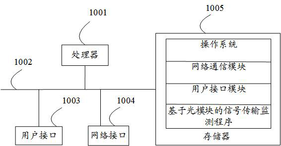
[0052] refer to figure 1 , figure 1 It is a schematic structural diagram of a signal transmission monitoring device based on an optical module in the hardware operating environment involved in the solution of the embodiment of the present invention.

[0053] Such as figure 1As shown, the optical module-based signal transmission monitoring device may include: a processor 1001 , such as a central processing unit (Central Processing Unit, CPU), a communication bus 1002 , a user interface 1003 , a network interface 1004 , and a memory 1005 . Wherein, the communication bus 1002 is used to realize connection and communication between these components. The user interface 1003 may include a display screen (Display). The optional user interface 1003 may also include a standard wired interface and a wireless interface. The w...


PUM


Abstract

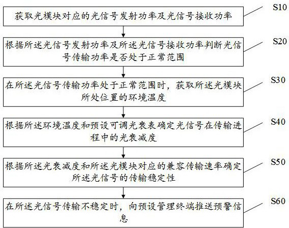
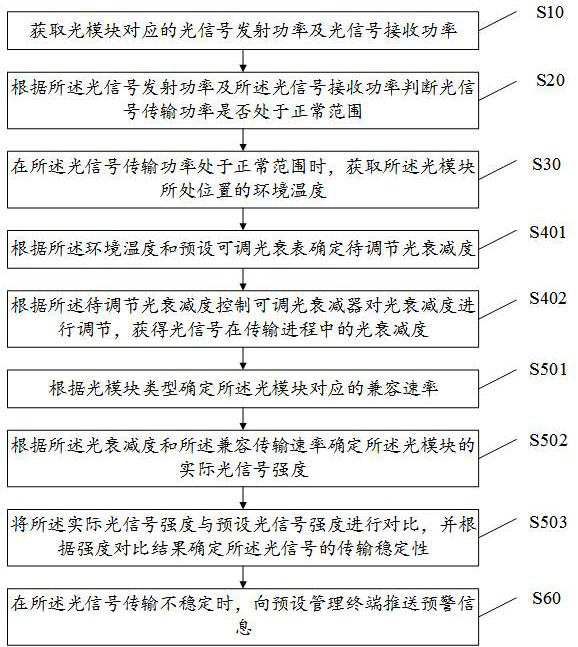
The invention discloses a signal transmission monitoring method, equipment, storage medium and device based on an optical module. The invention judges whether the transmission power of the optical signal is in the normal range according to the transmission power of the optical signal and the receiving power of the optical signal; In the normal range, the optical attenuation degree of the optical signal during the transmission process is determined according to the ambient temperature at the location of the optical module and the preset adjustable optical attenuation meter. The transmission rate determines the transmission stability of the optical signal. When the transmission is unstable, the early warning information is sent to the preset management terminal. Compared with the existing technology, the manual maintenance and detection of optical communication equipment leads to low detection and maintenance efficiency and affects the information transmission efficiency. , The user experience is poor, and the present invention improves the detection and maintenance efficiency, reduces information error transmission, and improves user experience.

Description

technical field [0001] The invention relates to the field of signal monitoring, in particular to a signal transmission monitoring method, equipment, storage medium and device based on an optical module. Background technique [0002] At present, with the gradual development of the communication network, the original signal is transmitted by electricity through the cable. As the transmission distance increases, the higher the frequency, the greater the loss, and the more severe the signal deformation, which causes the receiver to make a wrong judgment and lead to communication failure. [0003] Therefore, the form of electrical signal transmission through cables is gradually replaced by optical module transmission. Since the optical module integrates the transmitter and receiver into a package module and becomes an integrated transceiver module, the maintenance of the optical module Detection is particularly important. The existing technology is to regularly maintain and detec...

Claims


Application Information

Patent Timeline
Patent Type & Authority Patents(China)
IPC IPC(8): H04B10/079H04L41/06
CPCH04B10/07955H04B10/0795H04L41/06
Inventor 杨德瑞鲁光辉
Owner SHENZHEN FIBERTOP TECH CO LTD
Learn More