
Motor magnetic steel detection equipment

A technology of detection equipment and magnetic steel, which is applied in sorting and other directions, can solve the problems of poor detection safety, low detection efficiency, and difficult separation of magnetic steel, and achieve the effect of rapid detection

Active Publication Date: 2021-12-28
程俊峰
View PDF6 Cites 0 Cited by
  • Summary
  • Abstract
  • Description
  • Claims
  • Application Information

AI Technical Summary

Problems solved by technology

In the general production process, it is necessary to detect the magnetic flux of the magnets. Generally, workers need to pass the magnets one by one through the magnetic flux detection device for detection, and remove the magnets whose magnetic flux does not meet the requirements. Before the detection starts, the magnets are generally stacked. together, and due to the strong magnetic force of the magnets, the magnets are generally separated by pads, and after the magnets are removed, the pads on the side to be tested need to be placed on the side where the detection is completed, and then the magnets Stacking, this detection process is inefficient and consumes a lot of manpower
If there is a misoperation during the detection process, the two pieces of magnetic steel can easily pinch the inspector if they are in direct contact, and the detection safety is poor. It is also difficult to separate the two bonded magnetic steels, which further leads to low detection efficiency.

Method used


Image

  • Motor magnetic steel detection equipment
  • Motor magnetic steel detection equipment
  • Motor magnetic steel detection equipment

Examples


Embodiment Construction

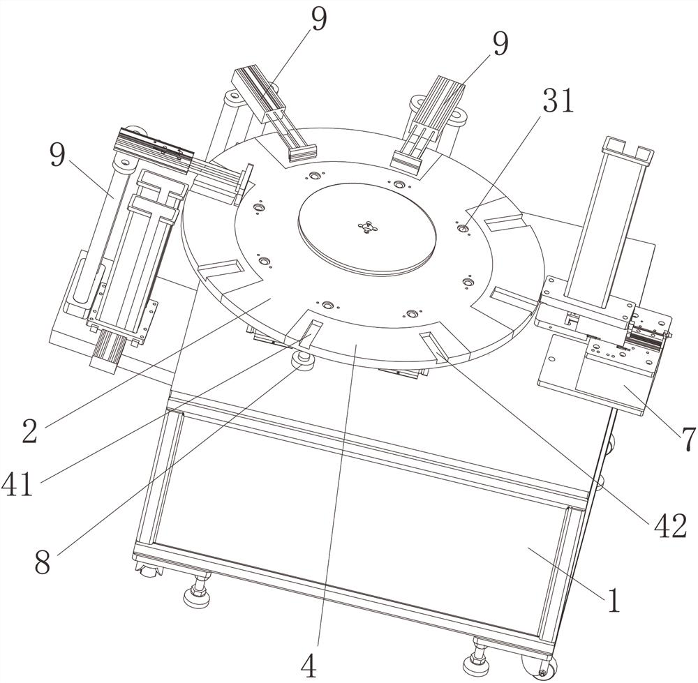
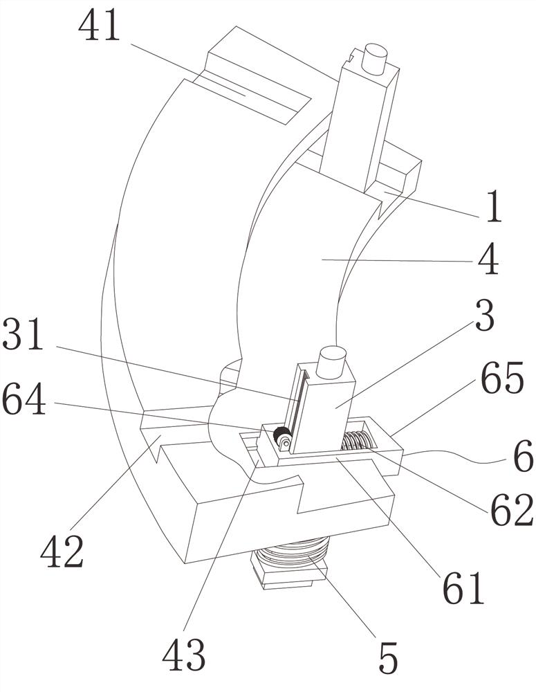
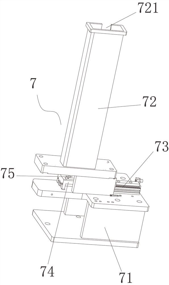
[0016] The present invention will be described in further detail below in conjunction with accompanying drawing and specific embodiment: see Figure 1 to Figure 5, a kind of motor magnetic steel detection equipment, comprises machine base 1, is provided with turntable 2 on machine base 1, and turntable 2 is driven by motor, and turntable 2 is provided with eight guide rods 3 with rack 31, and rack 31 guides The rod 3 is arranged axially, and the sliding sleeve on the guide rod 3 is provided with a lifting plate 4, and each lifting plate 4 is provided with two guide rods 3, and each lifting plate 4 is provided with a magnetic steel groove 41 and a spacer Groove 42, four lifting plates 4 are evenly arranged on the turntable 2, the magnetic steel groove 41 and the spacer groove 42 are evenly spaced on the turntable 2, and the magnetic steel upper surface and the spacer after the magnetic steel is built into the magnetic steel groove 41 The upper surface of the spacer after the sp...


PUM


Abstract

The invention discloses motor magnetic steel detection equipment which comprises a machine base. A rotating disc is arranged on the machine base, a plurality of guide rods are arranged on the rotating disc, lifting plates with axial racks are arranged on the guide rods in a sliding and sleeving mode, magnetic steel grooves and cushion block grooves are formed in the lifting plates, and first reset springs are arranged between the lifting plates and the bottoms of the guide rods. A sliding groove is further formed in each lifting plate, a retaining assembly is arranged in each sliding groove in a sliding mode, and a feeding mechanism, a magnet, at least three discharging mechanisms and an unlocking block are sequentially arranged on the machine base in the rotating direction of the rotating disc. The detection equipment can automatically classify and stack the magnetic steel with the magnetic flux meeting the requirement and the magnetic steel with the too large or too small magnetic flux, the magnetic steel is still separated by cushion blocks after detection is completed, and the detection efficiency and the detection safety are improved.

Description

technical field [0001] The invention belongs to the technical field of detection equipment for processing magnetic steel, in particular to a detection equipment for magnetic steel of a motor. Background technique [0002] NdFeB is a magnet with better performance used in motors. In the production process of this magnet, it needs to go through the steps of sintering and magnetization. Due to the uneven temperature in the sintering process and the magnetic field during magnetization Inconsistent strength and other issues will lead to a certain difference in the magnetic flux of the magnet. In the general production process, it is necessary to detect the magnetic flux of the magnets. Generally, workers need to pass the magnets one by one through the magnetic flux detection device for detection, and remove the magnets whose magnetic flux does not meet the requirements. Before the detection starts, the magnets are generally stacked. together, and due to the strong magnetic force...

Claims


Application Information

Patent Timeline
Patent Type & Authority Applications(China)
IPC IPC(8): B07C5/344B07C5/02B07C5/38
CPCB07C5/344B07C5/02B07C5/38
Inventor 程俊峰
Owner 程俊峰
Learn More