
Automatic blanking machining mechanism for material strap

A technology of automatic blanking and processing mechanism, applied in the field of blanking processing, can solve the problems of reducing processing efficiency, reducing precision, scrapping of material positions, etc., and achieves the effects of improving production efficiency, improving cleanliness, and improving accuracy

Pending Publication Date: 2021-12-28
光子(深圳)精密科技有限公司
View PDF9 Cites 1 Cited by
  • Summary
  • Abstract
  • Description
  • Claims
  • Application Information

AI Technical Summary

Problems solved by technology

[0004] 1. The existing blanking equipment cannot realize continuous feeding and discharging of objects during processing, and manual operation is required to control, which cannot realize assembly line production and reduces processing efficiency;
[0005] 2. When the existing blanking equipment is being processed, waste materials are piled up around the equipment, which needs to be cleaned regularly, and the separation of waste materials and articles cannot be realized, which makes the working environment of the staff more chaotic;
[0006] 3. When the existing punching equipment is being processed, most of the punching dies are mechanical clamping structures, and the clamping positioning is mainly judged by the naked eye, which is not only time-consuming and labor-intensive, but also reduces precision, and it is easy to cause scrap

Method used


Image

  • Automatic blanking machining mechanism for material strap
  • Automatic blanking machining mechanism for material strap
  • Automatic blanking machining mechanism for material strap

Examples


Embodiment Construction

[0030] The following will clearly and completely describe the technical solutions in the embodiments of the present invention with reference to the accompanying drawings in the embodiments of the present invention. Obviously, the described embodiments are only some, not all, embodiments of the present invention. Based on the embodiments of the present invention, all other embodiments obtained by persons of ordinary skill in the art without making creative efforts belong to the protection scope of the present invention.

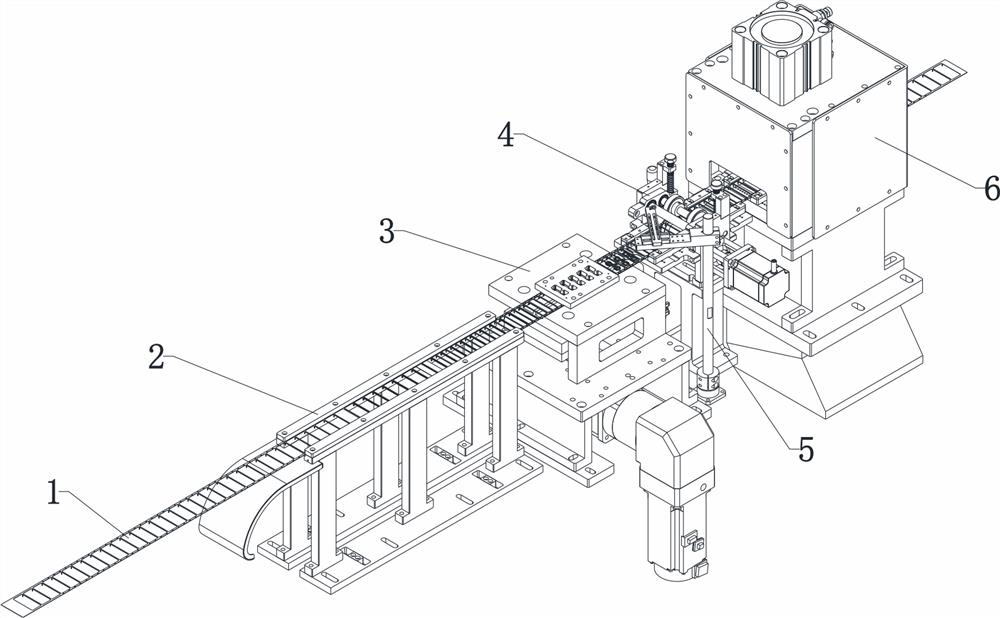
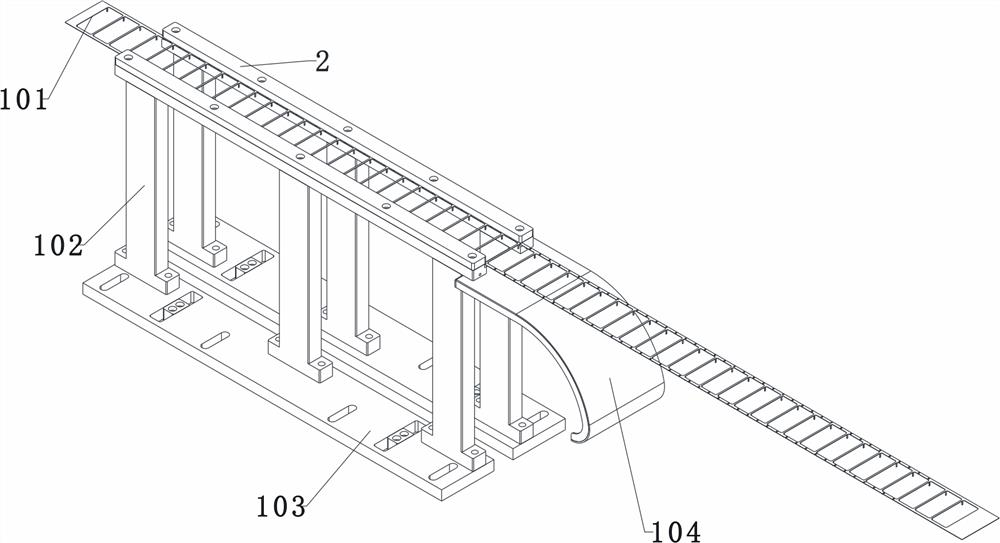
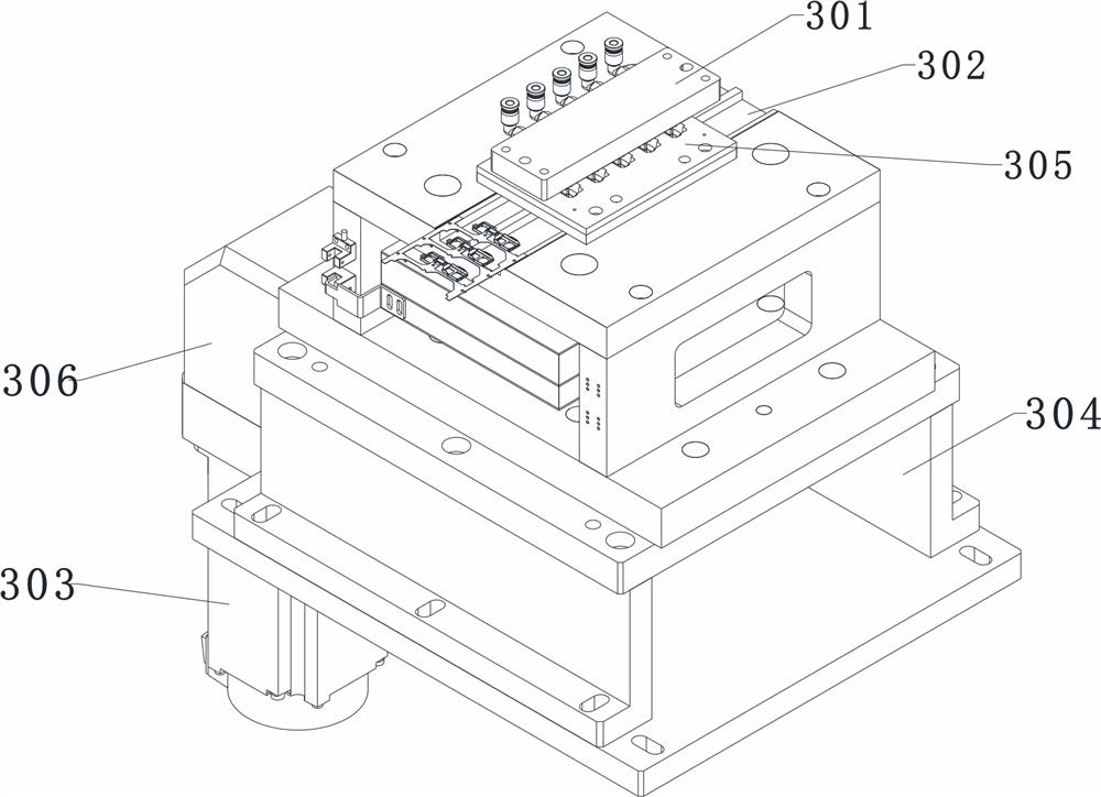
[0031] see Figure 1~6 , in an embodiment of the present invention, an automatic punching and processing mechanism for material strips, including a product material belt assembly 1, a conveying track 101 for an external drive mechanism is arranged on the product material belt assembly 1, and guide rails 101 are provided on the front and rear sides of the conveying track 101. The front side plate 2, the right side of the guide side plate 2 is provided with a pu...


PUM


Abstract

The invention discloses an automatic blanking machining mechanism for a material strap. The automatic blanking machining mechanism for the material strap comprises a product material strap assembly, wherein a conveying track externally connected with a driving mechanism is arranged on the product material strap assembly; guide side plates are arranged outside the front side and the rear side of the conveying track; a blanking mechanism is arranged on the right sides of the guide side plates; a feeding mechanism is arranged on the right side, away from the guide side plates, of the blanking mechanism; a main rotating shaft and a driven rotating shaft which are located on the upper side and the lower side of the conveying track are arranged on the feeding mechanism; second pressing plates fixed onto the feeding mechanism are arranged on one sides of the exteriors of the main rotating shaft and the driven rotating shaft; an in-place monitoring mechanism is arranged over the feeding mechanism; an optical fiber lens is arranged on the in-place monitoring mechanism; and a waste cutting mechanism is arranged on the right side, away from the blanking mechanism, of the feeding mechanism. According to the automatic blanking machining mechanism for the material strap provided by the invention, continuous blanking machining of blanking products can be achieved, the functions of feeding, charging and discharging are automatically achieved, and compared with traditional blanking equipment controlled manually, the production efficiency is greatly improved through the automatic blanking machining mechanism.

Description

technical field [0001] The invention relates to the technical field of punching processing, in particular to an automatic punching processing mechanism for material strips. Background technique [0002] Punching processing is a stamping processing method that uses a mold to separate the sheet metal. Punching can not only obtain flat parts, but also prepare blanks for bending, deep drawing, forming and other processes. It is to use the cutting edge of the die to cause the sheet to shear deformation and separate along a certain contour line. Blanking accounts for the largest proportion in stamping production. In the blanking process, except for the metal near the shear contour line, the sheet itself does not produce plastic deformation, so the parts processed by flat plate blanking are still in a flat shape. [0003] Existing blanking processing equipment has the following disadvantages: [0004] 1. The existing blanking equipment cannot realize continuous feeding and disc...

Claims


Application Information

Patent Timeline
IPC IPC(8): B21D28/14B21D43/00B21D43/20
CPCB21D28/14B21D43/003B21D43/20Y02P70/10
Inventor 姚文政张玉姚文朝杨远红唐磊
Owner 光子(深圳)精密科技有限公司
Learn More