In-mold cutting injection mold

An injection mold and in-mold cutting technology, applied in the field of molds, can solve the problems of reducing the service life of the mold, jamming, and inability to completely hide the incision, so as to achieve the effect of beautiful appearance and avoid pulling the cylinder.

Pending Publication Date: 2021-12-28
ZHEJIANG KAIHUA MOLDS
View PDF5 Cites 0 Cited by
  • Summary
  • Abstract
  • Description
  • Claims
  • Application Information

AI Technical Summary

Problems solved by technology

[0003] The existing in-mold cutting technology cannot completely hide the incision. The existing cutting knives are all flaky structures, which are prone to cylinder pulling and knife jamming when the cutting knives are ejected, reducing the service life of the mold

Method used


Image

  • In-mold cutting injection mold
  • In-mold cutting injection mold
  • In-mold cutting injection mold

Examples


Embodiment 1

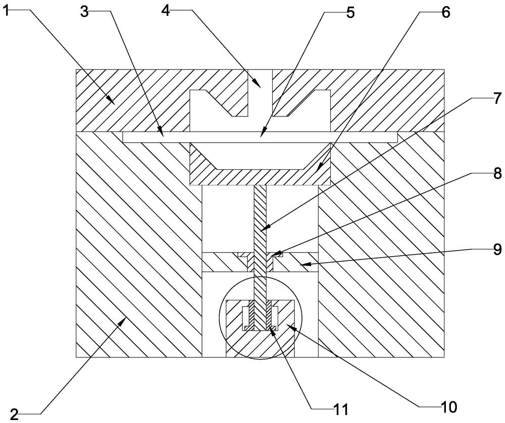
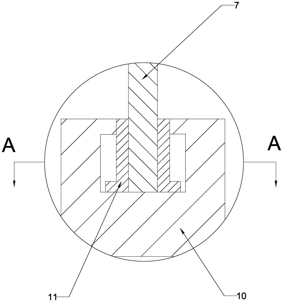
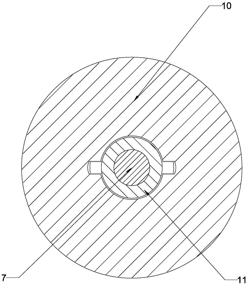
[0023] Such as figure 1 , figure 2 , image 3 In the shown embodiment, an in-mold cutting injection mold includes an upper mold core 1 and a lower mold core 2, and is characterized in that it also includes a cutting knife 6, and the cutting knife includes a cylindrical blade body. It also includes a cutter ejection mechanism, the cutter ejection mechanism includes an ejector rod assembly and a drive assembly, and a cutter ejection mechanism cavity is arranged inside the lower mold core. The ejector rod assembly includes a screw rod 7 and a nut 8 , a nut holder 9 is fixed in the cavity of the cutter ejection mechanism, and the nut 8 is fixed on the nut holder 9 . The drive assembly includes a hydraulic motor 10, a sleeve 11 is fixed at one end of the screw 7, and a positioning protrusion is arranged on the sleeve, and a sleeve cavity matching the sleeve 11 is connected to the output shaft of the hydraulic motor. , the sleeve cavity is provided with a sliding groove matching...

Embodiment 2

[0025] Such as Figure 4 In the above embodiment, the difference from the first embodiment is that the driving assembly includes an oil cylinder 12 , and the screw rod 7 is connected to the oil cylinder 12 through a bearing 13 by sliding. The oil cylinder can drive the screw to eject and retract, and at the same time, under the action of the fixed nut, the screw can rotate to realize rotating ejection and rotating retraction, effectively avoiding the phenomenon of cylinder pulling and knife jamming.

Embodiment 3

[0026] Embodiment 3: Different from the embodiment, the drive assembly includes a motor, a sleeve is fixed at one end of the screw, a positioning protrusion is provided on the sleeve, and the output shaft of the motor is connected with the A sleeve cavity of the sleeve, the sleeve cavity is provided with a slide groove matching the positioning protrusion. The motor can drive the screw to rotate, and at the same time, under the action of the fixed nut, the screw moves up and down to realize the ejection and retraction actions.

[0027] As a preference,

[0028] The cylindrical cutter can directly form products with round holes while cutting the nozzle, eliminating the process of digging holes. At the same time, it can completely hide the nozzle and make the appearance more beautiful.

[0029] The usual ejection mechanism is driven by the cylinder to eject the ejector rod, which is prone to cylinder pulling and knife jamming. The screw nut is a ball screw structure, the screw ...


PUM


Abstract

The invention discloses an in-mold cutting injection mold. The in-mold cutting injection mold comprises an upper mold core and a lower mold core, and is characterized by further comprising a cutter, and the cutter comprises a cylindrical cutter body. The cylindrical cutter can directly form a product with a round hole while cutting off a water gap, the technological process of hole digging is omitted, meanwhile, the water gap can be completely hidden, and the appearance is more attractive.

Description

technical field [0001] The invention relates to the field of molds, in particular to an in-mold cutting injection mold. Background technique [0002] In-mold cutting is to integrate the cutter inside the mold. When the injection molding is completed and the pressure is maintained, the cutter is ejected to complete the nozzle cut. Compared with the artificial nozzle, the incision is more uniform and beautiful. [0003] The existing in-mold cutting technology cannot completely hide the incision. The existing cutting knives are all sheet-like structures, which are prone to cylinder pulling and knife jamming when the cutting knives are ejected, which reduces the service life of the mold. [0004] For example, a kind of "an injection mold in-cutting mechanism" disclosed in Chinese patent literature, its notification number is CN213733192U, includes a first in-mold cutting fixing plate, and is characterized in that: the lower end of the first in-mold cutting fixing plate The seco...

Claims


Application Information

Patent Timeline
Patent Type & Authority Applications(China)
IPC IPC(8): B29C45/26B29C45/38
CPCB29C45/2628B29C45/38
Inventor 梁正华梁凯林连明王华良
Owner ZHEJIANG KAIHUA MOLDS
Why Eureka
Try Eureka