Non-uniform-rigidity holding handle structure and manufacturing method

A manufacturing method and non-uniform technology, applied in manufacturing tools, manufacturing auxiliary devices, processing data acquisition/processing, etc., can solve problems such as finger discomfort and reduced work efficiency, and achieve improved grip comfort and high elastic modulus Effect

Active Publication Date: 2021-12-28
XI AN JIAOTONG UNIV
View PDF5 Cites 0 Cited by
  • Summary
  • Abstract
  • Description
  • Claims
  • Application Information

AI Technical Summary

Problems solved by technology

In order to maintain the function and shape of the handle, the grip handle of the same material is usually relatively hard, which puts a certain amount of pressure on the fingers, and the muscles and neurons of the fingers are relatively complex and sensitive. Using it under long-term pressure will cause discomfort in the fingers. comfort, thereby reducing productivity

Method used


Image

  • Non-uniform-rigidity holding handle structure and manufacturing method
  • Non-uniform-rigidity holding handle structure and manufacturing method
  • Non-uniform-rigidity holding handle structure and manufacturing method

Examples


Embodiment 1

[0058] A design and preparation method for a non-uniform rigidity grip handle (rotary handle), comprising the following steps:

[0059] Step 1, determine the shape and size of the grip handle (handle), including diameter D, shape, and thickness h;

[0060] Step 2, constructing the shell structure for gripping the handle (handle);

[0061] Step 3, constructing the foam structure of the gripping handle (rotary handle) in contact with the hand;

[0062]Step 4, select materials, and prepare non-uniform rigidity grip handles (rotary handles) through materials and 3D printing equipment.

[0063] Further, step 1 specifically includes:

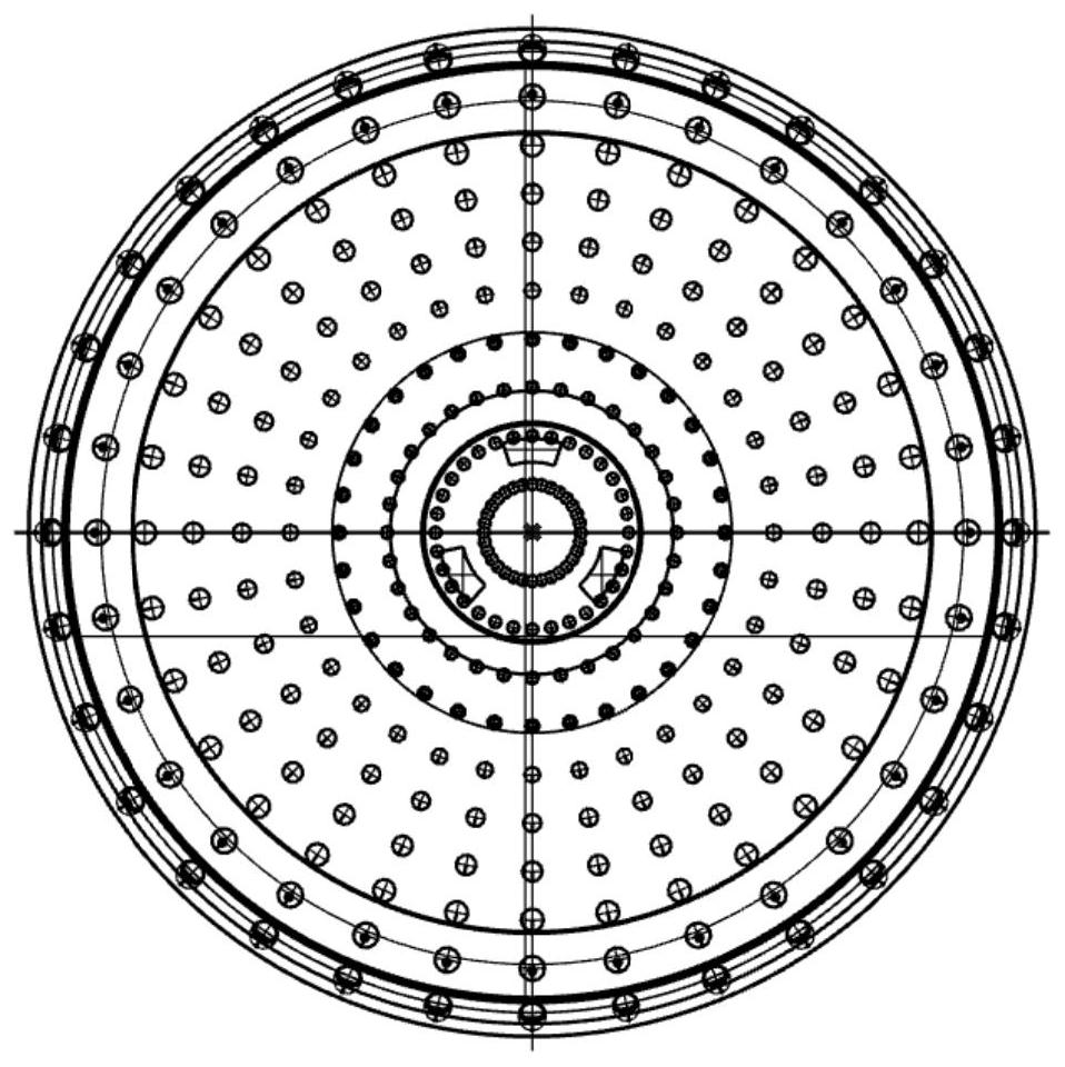
[0064] According to the size of the human hand is about 62-82mm, the diameter D of the handle (handle) is determined to be 75mm, the shape is round, and the thickness h is 17mm. figure 2 ;

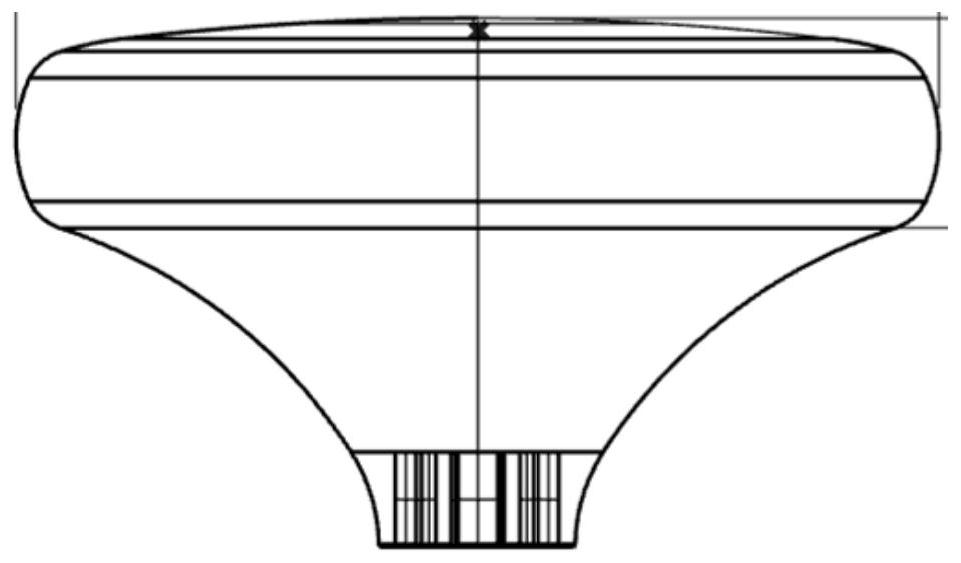
[0065] In the Solidworks modeling software, carry out the modeling of the grip handle (handle), set the diameter D, thickness h, and attach figure 1 .

[0...

Embodiment 2

[0085] A method for designing and manufacturing a handle with non-uniform stiffness, comprising the following steps:

[0086] Step 1. Determine the shape and size of the handle, including outer diameter D, inner diameter d, shape, and thickness h;

[0087] Step 2, build the shell structure to hold the handle;

[0088] Step 3, constructing the unit cell structure of the part of the handle that is in contact with the hand;

[0089] Step 4, select materials, and prepare grip handles with non-uniform stiffness through 3D printing equipment.

[0090] Further, step 1 specifically includes:

[0091] According to the size of the human hand is about 62-82mm, it is determined that the outer diameter D of the handle is about 35-40mm, the inner diameter d is 10-20mm, the shape is round, and the thickness h is about 10-15mm. figure 2 ;

[0092] Model the handle in Solidworks or RhinocerosCAD modeling software, set the outer diameter D, inner diameter d, shape, thickness h, and attach ...


PUM

PropertyMeasurementUnit
diameteraaaaaaaaaa
diameteraaaaaaaaaa

Abstract

The invention discloses a non-uniform-rigidity holding handle structure and a manufacturing method. The non-uniform-rigidity holding handle structure comprises a shell, an inner cylinder and a filling structure, wherein the inner cylinder is coaxially arranged in the shell, and the filling structure is fixedly arranged between the shell and the inner cylinder; and a screwdriver is fixedly arranged in the inner cylinder. The method comprises the following steps: S1, determining the shape and size of the holding handle, including diameter D, shape and thickness h; S2, constructing a shell structure of the holding handle; S3, constructing a foam structure or a cell element filling structure of the part, making contact with the hand, in the holding handle; and S4, selecting materials, and manufacturing the non-uniform-rigidity holding handle through 3D printing equipment. The shape and size of the holding handle are designed according to the size of the palm, the non-uniform-rigidity holding handle is manufactured at the position in contact with the hand by utilizing a TPU material and a 3D printing technology, and the holding comfort of the holding handle is improved by utilizing the foam structure or the cell element filling structure.

Description

technical field [0001] The invention belongs to the technical field of man-machine grip handle design, and in particular relates to a non-uniform stiffness grip handle structure and a manufacturing method. Background technique [0002] Tools are the extension of human limbs. The use of tools increases the range and strength of human movements and improves work efficiency. In our life, there are thousands of tools, large and small. In the process of using tools, in order to make the tools well utilized by people, we can not only make the tools play their role to the maximum, but also make the use of tools more efficient. The user feels very comfortable when using a tool, so the design of the handle on the tool is particularly important. The tool and the person are "connected" through the handle. A well-designed handle can not only make the tool play its function to the maximum, but also It can also make users less injured by tools. In order to make users use products safely,...

Claims


Application Information

Patent Timeline
Patent Type & Authority Applications(China)
IPC IPC(8): B29C64/386B25G1/10B33Y50/00
CPCB29C64/386B25G1/10B33Y50/00Y02T90/00
Inventor 李宏伟韩奇桂蓁蓉张创亮
Owner XI AN JIAOTONG UNIV
Why Eureka
Try Eureka