Main transmission device for strip wrapping machine

A technology of main drive and belting machine, applied in the direction of mechanical drive clutch, mechanical equipment, brake type, etc., can solve the problems of complex overall structure of belting machine, difficult manufacturing, processing and maintenance, etc., to ensure installation stability, guarantee Production processing and maintenance efficiency, the effect of ensuring work efficiency

Pending Publication Date: 2020-07-17
江苏安澜万锦电子股份有限公司
View PDF0 Cites 0 Cited by
  • Summary
  • Abstract
  • Description
  • Claims
  • Application Information

AI Technical Summary

Problems solved by technology

[0003] Most of the taping machines in the prior art are equipped with a separate transmission system, which makes the overall structure of the taping machine more complicated and difficult to manufacture, process and maintain.
The purpose of the patent of the present invention is to provide a main transmission device suitable for the taping machine, thereby effectively simplifying the overall structure of the taping machine, and solving the technical problems that the overall structure of the above-mentioned taping machine is relatively complex and difficult to manufacture, process and maintain.

Method used


Image

  • Main transmission device for strip wrapping machine
  • Main transmission device for strip wrapping machine
  • Main transmission device for strip wrapping machine

Examples


Embodiment 1

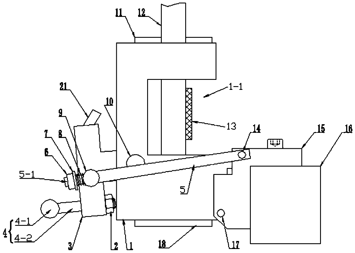
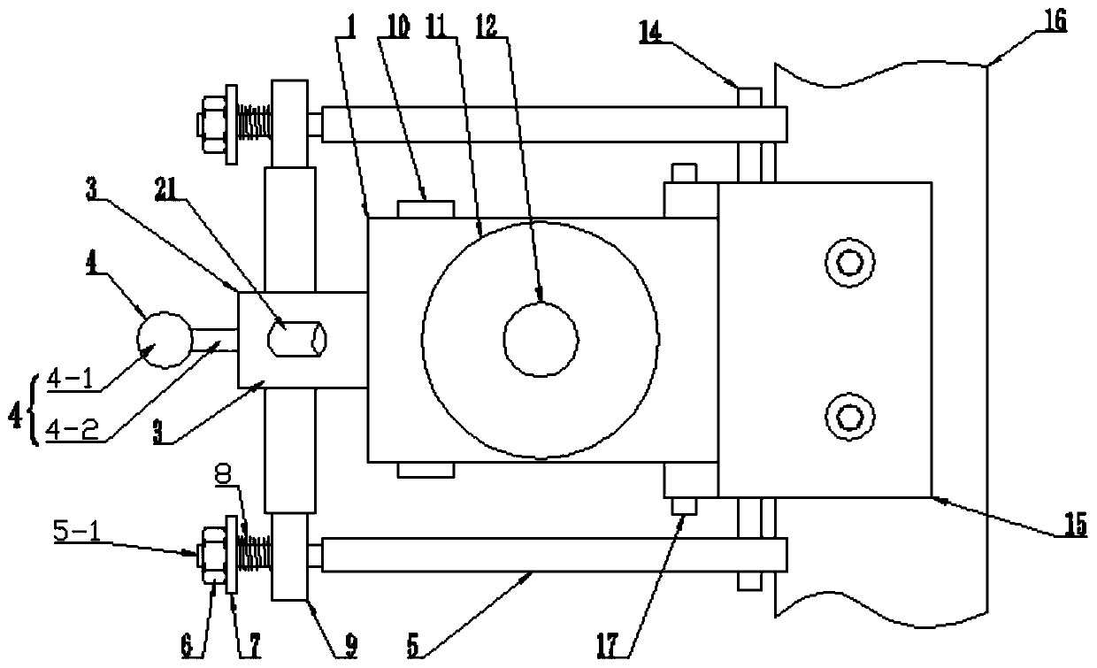
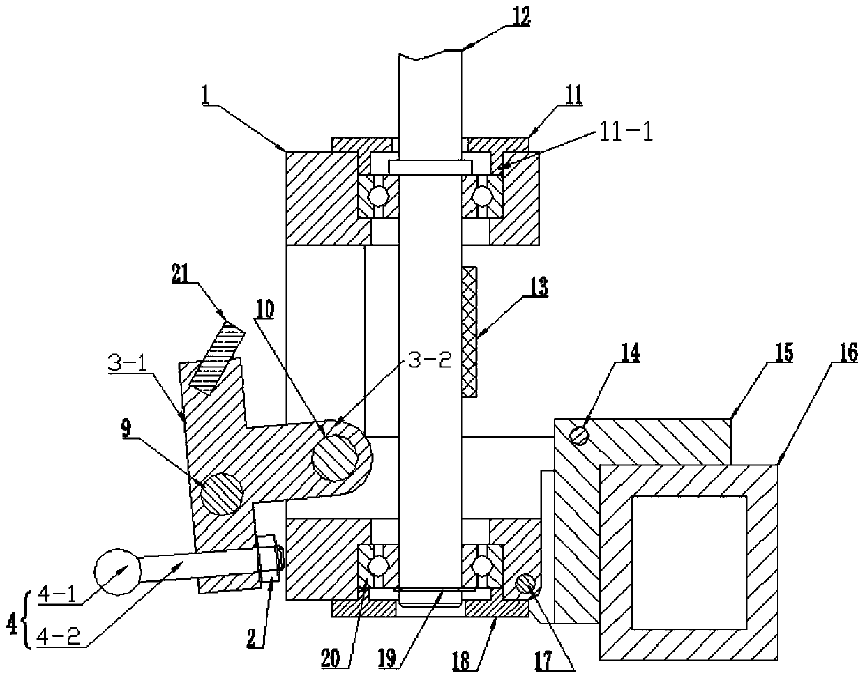
[0035] Such as Figure 1-8 As shown, a main transmission device suitable for a taping machine includes a crossbeam 16 and several transmission units, and several transmission units are detachably mounted on the crossbeam 16 at intervals, and the transmission unit includes a base 1, a main shaft 12 and a link mechanism, the main shaft 12 is vertically rotatably installed on the base 1, the lower side of the right end of the base 1 is rotatably installed on the lower end of the beam 16, and the right end of the link mechanism is rotatably connected with the upper end of the beam 16. The left end of the connecting rod mechanism is rotationally connected with the left end of the base 1, and the main shafts 12 of several transmission units are all connected to the transmission belt 13. Fitting transmission or disengagement, the main shaft 12 is provided with a line passing hole through the axis.

[0036] Preferably, the transmission unit further includes a first bracket 15, the fi...

Embodiment 2

[0047] Such as Figure 9As shown, a copper foil wrapping device is used to produce copper foil signal lines. The main transmission device described in Embodiment 1 is applied to the copper foil wrapping device. The upper end of the main shaft 12 is processed into a large bottom and a small top The tapered structure, the upper end of the main shaft 12 is sequentially sleeved with a tape storage cylinder 22, a tape assembly 23, a conical spring 25 and a fixed ring 24, and the tape storage cylinder 22 is provided with a tapered installation penetrating through the shaft center. hole, the fixed ring 24 is fixed on the upper end of the main shaft 12, the conical spring 25 is sleeved on the main shaft 12 between the fixed ring 24 and the strap assembly 23, and the fixed ring 24 passes through the conical spring 25 abutting and pressing the strap assembly 23 and the storage drum 22 .

[0048] As a preference, the strap assembly 23 includes a first bracket 23-2, a second bracket 23-4...


PUM


Abstract

The invention discloses a main transmission device for a strip wrapping machine. The main transmission device comprises a crossbeam and a plurality of transmission elements. The transmission elementsare detachably and fixedly mounted on the crossbeam at intervals, the transmission elements include bases, spindles and connecting rod mechanisms, the spindles are vertically and rotatably mounted onthe bases, the lower sides of the right ends of the bases are rotatably mounted on the lower end of the crossbeam, the right ends of the connecting rod mechanisms are rotatably connected to the upperend of the crossbeam, the left ends of the connecting rod mechanisms are rotatably connected to the left ends of the bases, the spindles the transmission elements are connected with a transmission belt in a transmission mode, the connecting rod mechanisms are used for controlling the joint transmission or detachment of the spindles of the transmission elements with the transmission belt, and wirethrough hole penetrating through axes are formed in the spindles. The structure design of the main transmission device is simple and reasonable, the synchronous operation of the multiple transmissionunits is driven by the transmission belt, the working efficiency of the strip wrapping machine equipment with the main transmission device is ensured, and each transmission unit can be controlled separately; and the structure design of the strip wrapping machine can be simplified, and the production, processing and maintenance efficiency of the strip wrapping machine can be guaranteed.

Description

technical field [0001] The invention relates to the technical field of cable production equipment, in particular to a main transmission device suitable for a taping machine. Background technique [0002] The taping machine is mainly composed of a taping device and a tape unwinding device, wherein the tape wrapping device is responsible for winding the tape material onto the core wire, and the tape unwinding device is responsible for outputting the tape material. The tape is generally stored in the tape storage drum of the tape unwinding device, and the tape storage drum can be rotated to output the tape, and the output speed of the tape must match the winding speed of the taping device to ensure the normal operation of the tape. [0003] Most of the taping machines in the prior art are separately equipped with a transmission system, so that the overall structure of the taping machine is relatively complicated, and the manufacturing, processing and maintenance are relatively ...

Claims


Application Information

Patent Timeline
Patent Type & Authority Applications(China)
IPC IPC(8): F16D13/20F16D49/00H01B13/00F16D121/14
CPCF16D13/20F16D49/00F16D2121/14H01B13/0036
Inventor 李伟朱军伟杨阳吴云胜王江辉潘伟李永生王传奇李春涛蒋晓波陆宇奇梁建峰杨小斌丁仕燕
Owner 江苏安澜万锦电子股份有限公司
Why Eureka
Try Eureka