A central supply and distribution control device for building hot water based on new energy technology
What is Al technical title?
Al technical title is built by PatSnap Al team. It summarizes the technical point description of the patent document.
A control device and new energy technology, which is applied to solar collector controllers, solar thermal energy, solar thermal power generation, etc., can solve problems such as reducing reflection efficiency, fast heat dissipation, and hindering personnel from observing, so as to improve observation effect and reduce work volume effect
Active Publication Date: 2022-04-12
陕西宇隆伟业节能环保科技有限公司
View PDF13 Cites 0 Cited by
Summary
Abstract
Description
Claims
Application Information
AI Technical Summary
This helps you quickly interpret patents by identifying the three key elements:
Problems solved by technology
Method used
Benefits of technology
Problems solved by technology
[0003] The existing building hot water central supply and distribution control device is not equipped with an automatic water level alarm device. Usually, the personnel's eyes are used to observe the level of the water level, which increases the workload of the personnel. It hinders the observation of personnel, and it is also easy to burn personnel. When the existing building hot water central supply and distribution control device is heating water, it usually heats the water through the irradiation of the reflector. However, the general reflector is usually fixed. It can only reflect sunlight from one aspect, which reduces the reflection efficiency and has a low scope of application. The existing building hot water central supply and distribution control device is not equipped with thermal insulation protection devices, resulting in faster heat dissipation of hot water at night. Thereby reducing the use efficiency of hot water and making it inconvenient for personnel to use
Method used
Image
Click on the blue label to locate the original text in one second.
Reading with bidirectional positioning of images and text.
Examples
Embodiment Construction
[0022] In order to make the technical means, creative features, goals and effects achieved by the present invention easy to understand, the present invention will be further described below in conjunction with specific embodiments.
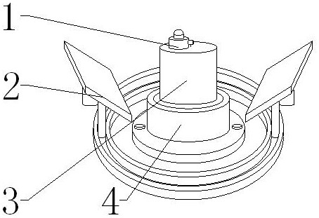
[0023] see Figure 1-Figure 4 , the present invention provides a technical solution: a central hot water supply and distribution control device for buildings based on new energy technology, including an alarm mechanism 1, an irradiation mechanism 2, a device body 3 and a protection mechanism 4, and the device body 3 is installed at the lower end of the alarm mechanism 1 The lower end of the device main body 3 is provided with a protective mechanism 4, and the alarm mechanism 1, the device main body 3 and the protective mechanism 4 are all assembled inside the irradiation mechanism 2.
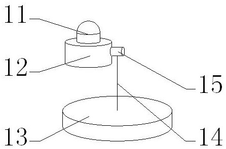
[0024] Alarm mechanism 1 comprises alarm light 11, mobile power supply 12, floating plate 13, stay cord 14 and pull switch 15, and mobile power supply 12 is install...
PUM
Abstract
The invention provides a building hot water central supply and distribution control device based on new energy technology, including an alarm lamp, a mobile power supply, a floating plate, a pull cord, a pull switch, a reflector, a sliding groove, a sliding rod, a supporting rod, and a moving rod , ring chute, thermal insulation cotton and hollow base, a mobile power supply is installed at the lower end of the alarm light, a pull switch is installed at the right end of the mobile power supply, a pull rope is installed at the lower end of the pull switch, and a floating plate is connected to the lower end of the pull rope. This design can be used for alarming, and the lower end of the reflector The sliding groove is installed, the moving rod is installed at the lower end of the support rod, and the moving rod is installed at the upper end of the annular chute, and the supporting rod is connected with the sliding groove through the sliding rod. The main body of the device is used for heat preservation. The invention is convenient to use, easy to operate, capable of automatic alarm, movable and protective.
Description
technical field [0001] The invention relates to a building hot water central supply and distribution control device based on new energy technology, and belongs to the field of new energy technology. Background technique [0002] The normal and reasonable supply of hot water in the existing college student apartments and other places has always been a problem that plagues the industry. Therefore, providing solar energy and wind energy to hotels, college student apartments and other places has become a research direction. [0003] The existing building hot water central supply and distribution control device is not equipped with an automatic water level alarm device. Usually, the personnel's eyes are used to observe the level of the water level, which increases the workload of the personnel. It hinders the observation of personnel, and it is also easy to burn personnel. When the existing building hot water central supply and distribution control device is heating water, it usu...
Claims
Application Information
Patent Timeline
Application Date:The date an application was filed.
Publication Date:The date a patent or application was officially published.
First Publication Date:The earliest publication date of a patent with the same application number.
Issue Date:Publication date of the patent grant document.
PCT Entry Date:The Entry date of PCT National Phase.
Estimated Expiry Date:The statutory expiry date of a patent right according to the Patent Law, and it is the longest term of protection that the patent right can achieve without the termination of the patent right due to other reasons(Term extension factor has been taken into account ).
Invalid Date:Actual expiry date is based on effective date or publication date of legal transaction data of invalid patent.