

Template printing device with deviation rectifying mechanism
A stencil printing and equipment technology, applied in printing, printing machines, rotary printing machines, etc., can solve the problems affecting the movement of the limit ring and unfavorable stencil limit, and achieve the effect of speeding up the movement
- Summary
- Abstract
- Description
- Claims
- Application Information
AI Technical Summary
Problems solved by technology
Method used
Image

Examples
Embodiment 1
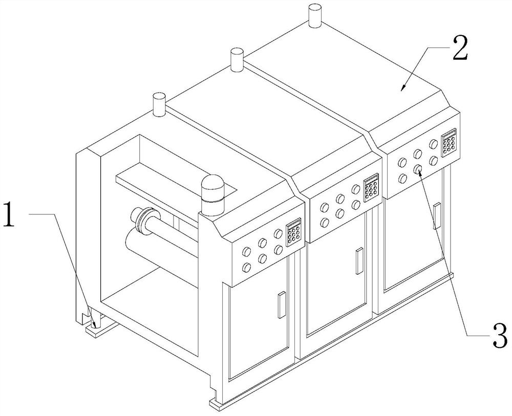
[0029] as attached figure 1 To attach Figure 6 Shown:
[0030] The present invention provides a stencil printing device with a deviation correcting mechanism, the structure of which includes a base 1, a body 2, and a control panel 3, the bottom of the body 2 is vertically welded to the top surface of the base 1, and the control panel 3 is arranged on the right side of the body 2 surface.
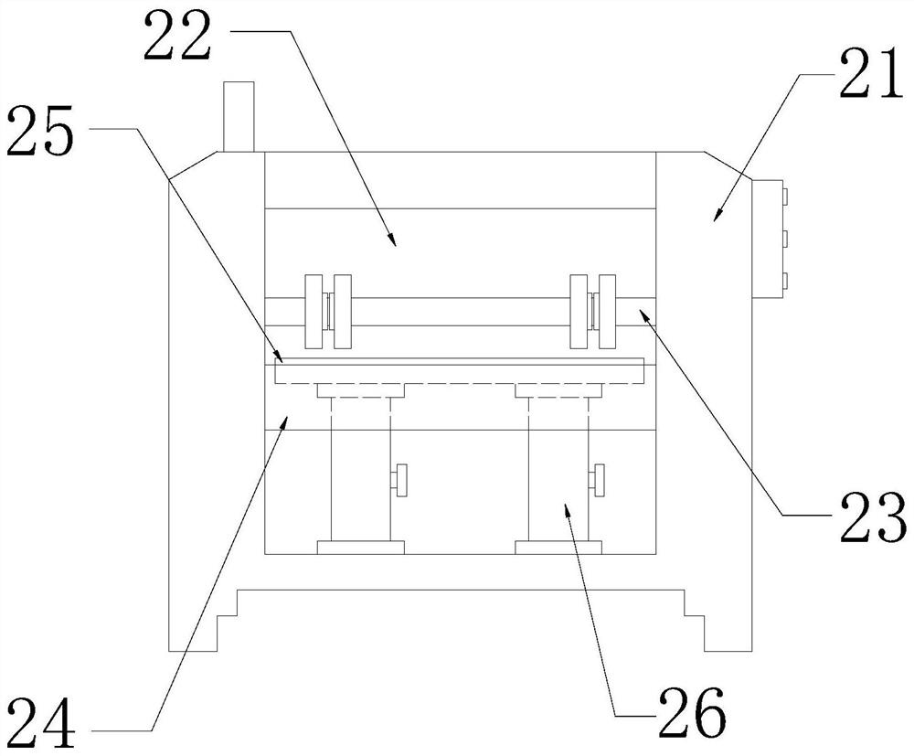
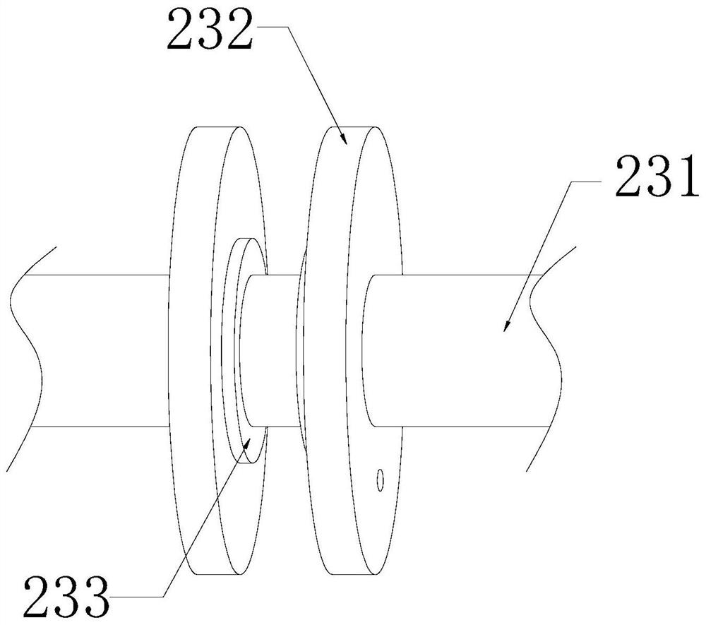
[0031] The body 2 includes a housing 21, a printing chamber 22, a limit rod 23, a printing roller 24, a support plate 25, and a deviation correction mechanism 26. The ends are respectively connected to the surfaces on both sides of the printing chamber 22, the printing roller 24 is located below the limit rod 23, the support plate 25 is arranged on the back of the printing roller 24, and the upper and lower ends of the correction mechanism 26 are respectively installed on the bottom surface of the support plate 25. And between the bottom of the printing chamber 22.
[0032] Wherein, the...
Embodiment 2
[0039] as attached Figure 7 to attach Figure 9 Shown:
[0040] Wherein, the movable cavity c3 includes a cover plate c31, a matching plate c32, a bottom groove c33, and a cleaning ring c34. Through the upper and lower surfaces of the middle part of the cover plate c31, the clearing ring c34 is movably matched with the matching plate c32. There are two matching plates c32, which are symmetrically distributed on the left and right, which is beneficial for the matching plate c32 to continuously move and cooperate with the clearing ring c34, evenly Remove the particles remaining outside the cleaning ring c34 to keep the outer wall of the cleaning ring c34 clean.
[0041] Wherein, the clearing ring c34 includes a support ring r1, an elastic block r2, and a scraper r3, the inner end of the elastic block r2 is connected to the outer wall of the support ring r1, and the inner surface of the scraper r3 is attached to the outer surface of the elastic block r2 , the scraper r3 is ma...
PUM
 Abstract
Description
Claims
Application Information