Pipe limiting devices and pipe lifting equipment

A technology for limiting devices and pipe fittings, applied in the directions of transportation, packaging, conveyors, etc., can solve the problems of pipe fittings slipping, poor pipe compatibility, and insufficient restrictions, avoiding shaking, improving shape fit, and improving compatibility. Effect

Pending Publication Date: 2021-12-28
ZHEJIANG SORFA MEDICAL PLASTIC
View PDF1 Cites 0 Cited by
  • Summary
  • Abstract
  • Description
  • Claims
  • Application Information

AI Technical Summary

Problems solved by technology

However, in this patent, the pipes can just be accommodated between two adjacent lifting plates, and the surface on the lifting plates used to carry the pipes is a plane. Use force to ensure that the pipe will not slip out of the space between the two lifting plates. Obviously, the pipe is not sufficiently restrained. If the quality of the pipe to be transported is light, once the lifting device vibrates, the pipe will easily slip off the lifting plate; At the same time, in order to ensure that there is friction between the two lifting plates and the pipe, the distance between the two lifting plates is equal to the maximum width of the pipe, resulting in poor compatibility of the lifting structure for pipes of different sizes

Method used


Image

  • Pipe limiting devices and pipe lifting equipment
  • Pipe limiting devices and pipe lifting equipment
  • Pipe limiting devices and pipe lifting equipment

Examples


Embodiment Construction

[0034] The following detailed description is merely the limitation of the invention, which will be a modification of the present embodiment without creative contributions to this embodiment after reading the present invention after reading the present invention. It is required to be protected by patent law.

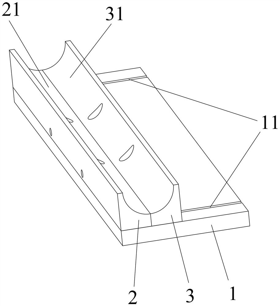
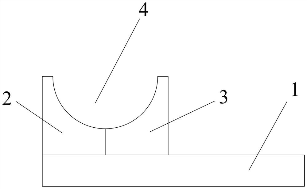
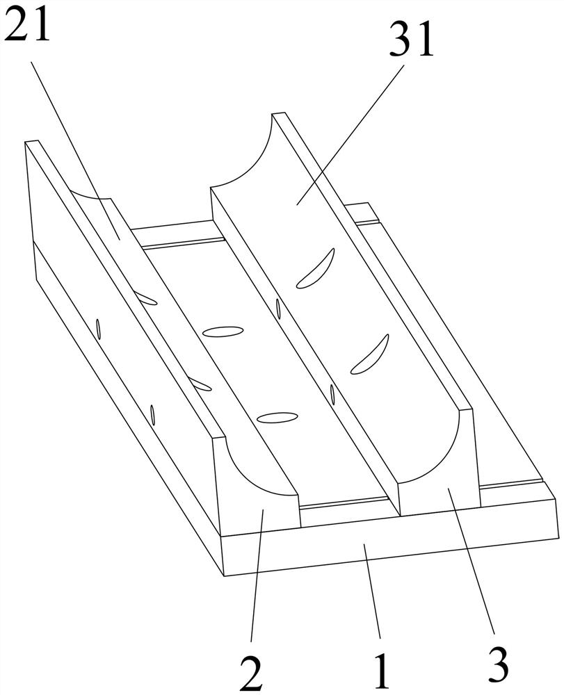
[0035] figure 1 A tube restricted device of the present invention is shown, including a base mounting plate 1, a front carrier holder 2 and a rear carrier 3, and a rear carrier 3, which are arranged on the base mounting plate 1, and the front carrier holder 2 has a support. The front support surface 21 of the pipe has a rear support surface 31 for supporting the tubing, and a housing groove 4 for limiting the tubing is formed between the front support surface 21 and the rear support surface 31. The tubular limit device A is mainly used to limit and carry the tube member in the lifting device, and the tube member is lifted, so the tube restricted device A needs to be fixed to...


PUM


Abstract

The invention relates to the technical field of pipe conveying, in particular to pipe limiting devices and pipe lifting equipment. The pipe limiting devices comprise base installation plates, front bearing seats and rear bearing seats, wherein the front bearing seats and the rear bearing seats are arranged front and back, and are installed on the base installation plates, the front bearing seats are provided with front bearing faces used for bearing pipes, the rear bearing seats are provided with rear bearing faces used for bearing the pipes, and containing grooves used for limiting the pipes are formed between the front bearing faces and the rear bearing faces. According to the pipe limiting devices and the pipe lifting equipment, the containing grooves have good limiting effects on the pipes so that a conveying belt can be preferably in a vertical state, and the space occupied by the equipment in the surrounding area is reduced; moreover, the possibility that the pipes slide down from the containing grooves due to external accidental factors can be avoided, and the anti-interference performance of the pipe limiting devices on the pipe limiting effects is improved; and meanwhile, the distance between the adjacent pipe limiting devices can be controlled within a large range so that the various pipes of different specifications can all fall into the containing grooves, and the compatibility of the pipe lifting equipment to the pipes of different specifications is improved.

Description

Technical field [0001] The present invention relates to the field of tubular delivery techniques, and more particularly to a pipe restricted device and a tubular lifting device. Background technique [0002] In industrial production, all types of tubes are typically cut into a plurality of lengths of tubular members in a certain aspect of production, because the tubular members obtained are the products that are sold and actually used, so they are generally cutting. The obtained pipes also need to be subsequent as follows of surface treatment, quality testing. The tubular members after the cutting are scattered, and it is difficult to carry out unified and orderly subsequent processes, so it is necessary to arrange them sequentially to provide convenience for subsequent processing. There are many equipment that are sequentially transported in the market, and a pipe fittings disclosed in China's patents, including pipe fittings, tubular lifting structures, and tubular rows, includ...

Claims


Application Information

Patent Timeline
Patent Type & Authority Applications(China)
IPC IPC(8): B65G17/12B65G17/36B65G17/46
CPCB65G17/123B65G17/36B65G17/46B65G2201/0217
Inventor 孙晓晓谢小良蒋峥嵘蒋险峰徐妙眉阳小春陈刚胜
Owner ZHEJIANG SORFA MEDICAL PLASTIC
Why Eureka
Try Eureka