Portable battery camera
A portable, battery-based technology, applied in the camera, camera body, optics, etc., can solve problems such as inconvenience of carrying, and achieve the effect of improving compatibility, improving convenience, and simple and fast process.
- Summary
- Abstract
- Description
- Claims
- Application Information
AI Technical Summary
Problems solved by technology
Method used
Image

Examples
Embodiment Construction
[0032] In order to make the purpose, technical solutions and advantages of the embodiments of the present invention more clear, the technical solutions in the embodiments of the present invention will be clearly and completely described below in conjunction with the accompanying drawings in the embodiments of the present invention. Obviously, the described embodiments It is a part of embodiments of the present invention, but not all embodiments. Based on the embodiments of the present invention, all other embodiments obtained by persons of ordinary skill in the art without making creative efforts belong to the protection scope of the present invention.
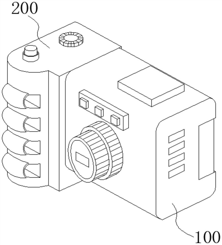
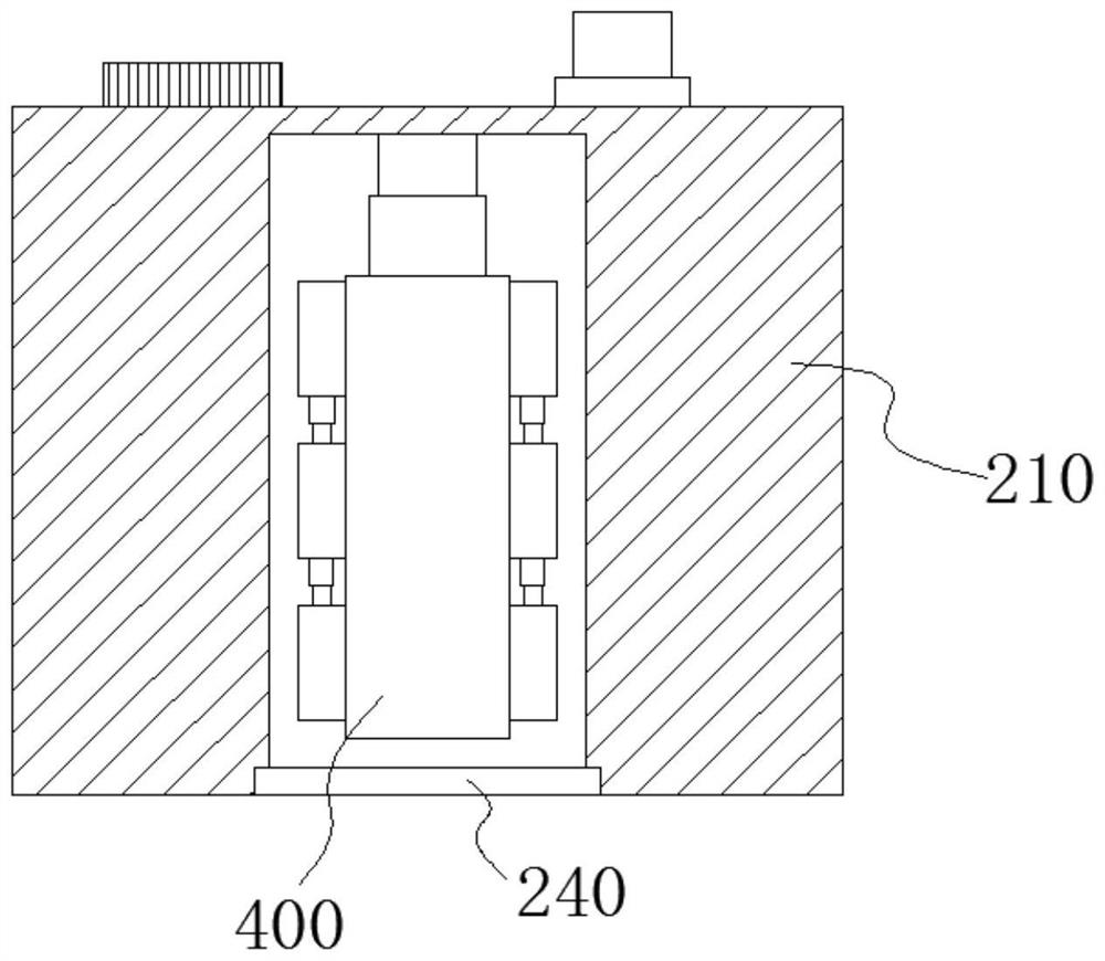
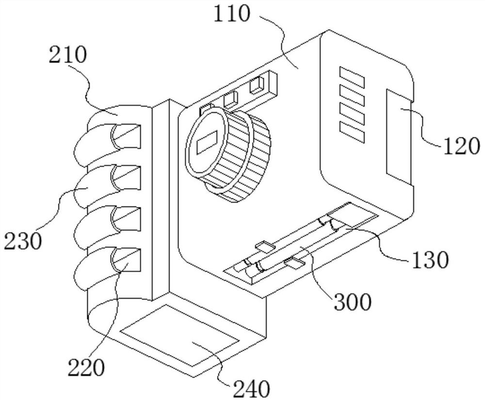
[0033] An embodiment of the present invention provides a portable battery camera, including a battery camera module 100 , an auxiliary unit 200 , a telescopic support unit 300 and a folding frame unit 400 . Exemplary, such as figure 1 , figure 2 with image 3 As shown, the housing of the auxiliary unit 200 is fixedly insta...
PUM
 Abstract
Description
Claims
Application Information