Class-specified multi-mode joint representation method for large-scene remote sensing image classification

A technology for remote sensing images and large scenes, applied in the field of joint representation of multi-mode remote sensing images, to achieve good discrimination, improved classification performance, and high classification accuracy

Active Publication Date: 2021-12-28
HARBIN INST OF TECH
View PDF4 Cites 1 Cited by
  • Summary
  • Abstract
  • Description
  • Claims
  • Application Information

AI Technical Summary

Problems solved by technology

[0004] The purpose of the present invention is to improve the classification accuracy of the existing large-scene remote sensing ima

Method used


Image

  • Class-specified multi-mode joint representation method for large-scene remote sensing image classification
  • Class-specified multi-mode joint representation method for large-scene remote sensing image classification
  • Class-specified multi-mode joint representation method for large-scene remote sensing image classification

Examples


specific Embodiment approach 1

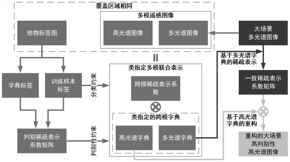
[0023] Specific implementation mode one: combine figure 1 This embodiment is described. In this embodiment, a class-specified multi-mode joint representation method for remote sensing image classification of large scenes is described in detail as follows:

[0024] Step 1. Input the multi-mode remote sensing image with the same coverage area, and the corresponding feature label map (both H and G in the formula are obtained based on this feature label map), and construct the class-specified multi-mode joint of the multi-mode remote sensing image Representation model, mainly including reconstruction error constraints, discriminative constraints and classification constraints;

[0025] The multimode remote sensing images include multispectral remote sensing images and hyperspectral remote sensing images;

[0026] The model optimization of step 2 and step 1 is based on the idea that the zero point of the first-order derivative of the constraint model is the extreme point, and the ...

specific Embodiment approach 2

[0031] Specific embodiment two: the difference between this embodiment and specific embodiment one is: in the described step one, construct the class-specified multi-mode joint representation model of the multi-mode remote sensing image; the specific process is:

[0032] make and Respectively represent the set of labeled samples in the hyperspectral and multispectral remote sensing images with the same coverage area of ​​the input, and these samples are the samples of the class-specified multi-mode joint representation;

[0033] make and Represent hyperspectral dictionary and multispectral dictionary respectively;

[0034] Let X denote the cross-modal sparse representation coefficient matrix;

[0035] in, Represents a labeled sample in a hyperspectral image, Denotes a labeled sample in a multispectral image, d H Indicates the spectral dimension of the sample in the hyperspectral image, d M Indicates the spectral dimension of the sample in the multispectral image,...

specific Embodiment approach 3

[0041] Embodiment 3: The difference between this embodiment and Embodiment 1 or 2 is that the class of the multi-mode remote sensing image specifies the first two items in the objective function of the multi-mode joint representation model Represents the reconstruction error, the third term α||X|| 1,1 Represents the sparsity constraint of the cross-mode sparse representation coefficient, the fourth term β(||D H || * +||D M || * ) represents the low-rank constraint of the cross-modulus dictionary, and the fifth item Represents discriminative constraints, the sixth term Represents a classification constraint.

[0042] Other steps are the same as those in Embodiment 1 or 2.


PUM


Abstract

The invention discloses a class-specified multi-mode joint representation method for large-scene remote sensing image classification, and relates to a multi-mode remote sensing image joint representation method. The objective of the invention is to improve the precision of existing large-scene remote sensing image classification. The method comprises the following steps of: 1, inputting multi-mode remote sensing images with the same coverage area and a corresponding ground object label map, and constructing a class-specified multi-mode joint representation model of the multi-mode remote sensing images, the multi-mode remote sensing images comprising multispectral remote sensing images and hyperspectral remote sensing images; 2, solving the class-specified multi-mode joint representation model of the multi-mode remote sensing images by adopting a multiplier alternating direction method to obtain a class-specified cross-mode dictionary; 3, inputting a large-scene multispectral remote sensing image, performing sparse representation on the input large-scene multispectral remote sensing image by using a multispectral dictionary, and learning to obtain a consistent sparse representation coefficient matrix; and 4, reconstructing to obtain a large-scene high-discrimination hyperspectral image. The method is applied to the field of remote sensing image classification.

Description

technical field [0001] The invention relates to a joint representation method of multi-mode remote sensing images. Background technique [0002] Fine classification of large scene remote sensing images is becoming more and more important in optical remote sensing applications. As two typical optical remote sensing data, multispectral images and hyperspectral images have complementary features: multispectral images have a large width and a short revisit period, but the number of bands is small, resulting in weak spectral separability. Hyperspectral images have narrow width and long revisit period, but they have hundreds of bands, so they have the ability of fine classification. In order to effectively utilize the advantages of multimodal remote sensing images (hyperspectral images and multispectral images), some scholars have studied the joint representation of multimodal remote sensing images in recent years. The relationship between the hyperspectral image and the multisp...

Claims


Application Information

Patent Timeline
IPC IPC(8): G06K9/00G06K9/62G06N20/00
CPCG06N20/00G06F18/214G06F18/241
Inventor 刘天竹谷延锋
Owner HARBIN INST OF TECH
Why Eureka
Try Eureka