Ocular surface positioner

A locator and ocular surface technology, which is used in stereotaxic surgical instruments, ophthalmic surgery, etc., can solve problems such as low measurement accuracy, achieve accurate positioning, convenient operation, and avoid inaccurate or inaccurate measurements.

Pending Publication Date: 2021-12-31
焦洁
View PDF0 Cites 0 Cited by
  • Summary
  • Abstract
  • Description
  • Claims
  • Application Information

AI Technical Summary

Benefits of technology

This technology provides an eye surgeon's tool called its visual aid (VAG). It consists of a special device made like a cup shape attached to a handle. Its top edge forms curved surfaces that fit into eyes without slipping off easily. There may also have holes near it where there will hold screws used to securely fix the VAG inside your own body. These features help improve accuracy when performing procedures such as cataract extraction and artificial implants.

Problems solved by technology

The technical problem addressed by this patented technology relates to improving eye surgery procedures that involve inserting artificial implants into eyes without causing damage caused by incorrect placement on the cornea due to poor alignment between the patient's eye socket and tools like screwdrivers or angled gears.

Method used


Image

  • Ocular surface positioner
  • Ocular surface positioner

Examples


Embodiment Construction

[0018] In order to describe the technical content, structural features, achieved goals and effects of the present invention in detail, the following will be described in detail in conjunction with the implementation and accompanying drawings. Based on the solution of the present invention, all other technical solutions obtained by persons of ordinary skill in the art without making creative efforts belong to the scope of protection of the present invention.

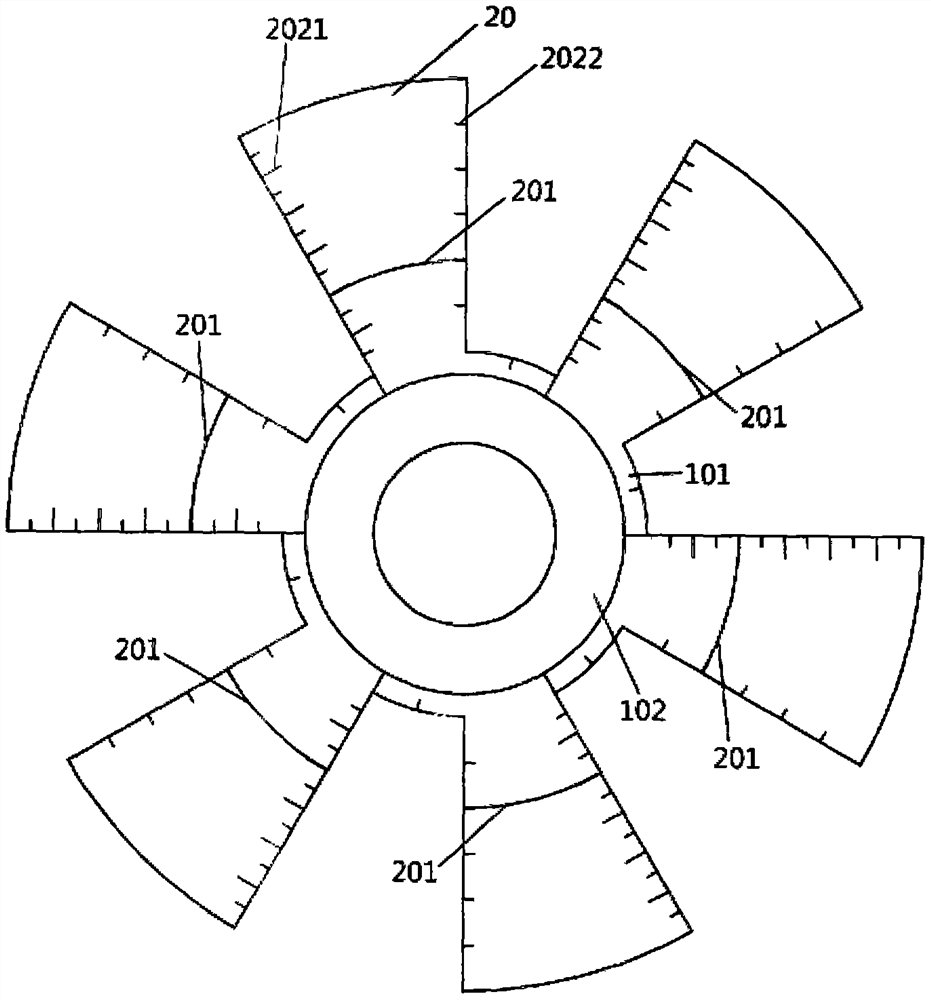
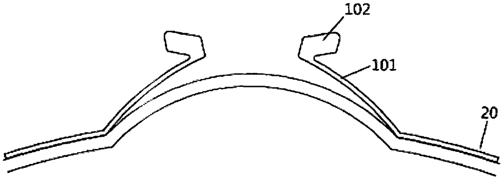
[0019] Such as figure 1 As shown, the present invention provides an ocular surface locator. The locator is in the shape of a dome as a whole, which is suitable for the structure of the ocular surface. The center of the locator is a hollow ring 101, which extends upward and turns outward to form an annular hand-held part 102. , the outer surface of the hand-held part 102 is an anti-slip thread, which can be clamped or held during the operation, and is convenient to operate; the hollow ring 101 is surrounded by fan-shaped b...


PUM

PropertyMeasurementUnit
Radiusaaaaaaaaaa

Abstract

The invention discloses an ocular surface positioner. The whole positioner is dome-shaped, the center of the positioner is of a hollow circular ring, the periphery of the hollow circular ring is of regularly arranged fan-shaped blades, the fan-shaped blades are radially arranged at a fixed included angle, corneal limbus marking lines are marked on the fan-shaped blades, the distance between the corneal limbus marking lines and the central point of the hollow circular ring is 6.0mm, the curvature from the corneal limbus marking lines to the central point of the hollow circular ring is 50, and the curvature radius of each outward blade of each corneal limbus marking line is 12.0mm. In clinical work of ophthalmology department, when accurate positioning is needed when an artificial lens is sutured and fixed or a ciliary body is sutured, accurate measurement and positioning can be achieved through the ocular surface positioner, operation is easy and convenient, precision is high, the operation time can be greatly shortened, and very high practicability is achieved.

Description


Claims


Application Information

Patent Timeline
Owner 焦洁
Why Eureka
Try Eureka